QUANTUM
™
HD COMPRESSOR CONTROL PANEL
MAINTENANCE
090.040-M (NOV 2016)
Page 27
ACTIVE LED
The Digital Boards have an Active LED indicator on the board
that blinks when the board’s software is running.
If the Active LED is not blinking, check to ensure that the
EPROM is installed properly. The EPROM is located in chip
slot U8, next to the power connector.
DIGITAL INPUTS
A Digital Input is the portion of the hardware that allows
devices such as limit switches, relay contacts, and level
switches, to interface with the Quantum™ HD. The software
program within the Quantum™ HD is constantly looking at
these Input channels, via communications, and based upon
whether a control voltage is present or not, will provide the
necessary control for an associated Output channel. For in-
stance, if a control voltage is present on the Oil Level Sensor
input, the software will determine that the Separator has
sufcient oil level for the oil heaters to be energized (if the
temperature of the oil is also sensed to be low. Temperature
sensing will be discussed in the Analog Input section).
There are two possible varieties of Digital Input modules
used on standard compressor control packages. One is for
120 Volt controls, and the other is for 230 volt controls. Both
of these module styles are yellow in color. A side prole of
these modules is shown below:
5 4 3
COM OUT VDC
2
~
1
90-140VAC
120 VAC
5 4 3
COM OUT VDC
2
~
1
180-280VAC
230 VAC
090.040-LD0006.eps
Figure 12. Digital Input Modules - Side View
These Input modules, can be identied as to their operating
voltage by looking at either the side, as shown above, or
from the top. You will notice the module operating voltage
printed on the top, and the voltage range printed on the side.
Never plug a 120 Volt Input module into a 230 Volt system,
and vice-versa. Never plug an Output module into a position
designated for an Input module.
You will notice that when a module is plugged into the Digital
board, there is a fuse located directly adjacent to the module.
This fuse is of the pluggable variety, and must be plugged
into the IN position for an Input module.
DIGITAL OUTPUTS
A Digital Output is the portion of the hardware that the
Q5 Processor Board is to control (energize). These devices
include solenoids, relay coils, and heaters to be energized,
based upon the logic within the Quantum™ HD software
program.
The Digital Output module used on standard compressor
control packages will handle both 120 Volt controls, and 230
volt controls. This module is black in color. A side prole of
this module is shown below:
Figure 13. Digital Output Module - Side View
4 3
3-8 VDC
2
~
1
3A 280VAC
120/230 VAC
090.040-LD0007.eps
Although this Output module is labeled as 280 VAC on the
top, and on the side, it can be used on both 120 and 230
volt applications.
Never plug an Input module into a position designated for
an Output module.
You will notice that when a module is plugged into the Digital
Board, there is a fuse located directly adjacent to the module.
This fuse is of the pluggable variety, and must be plugged
into the OUT position for an Output module.
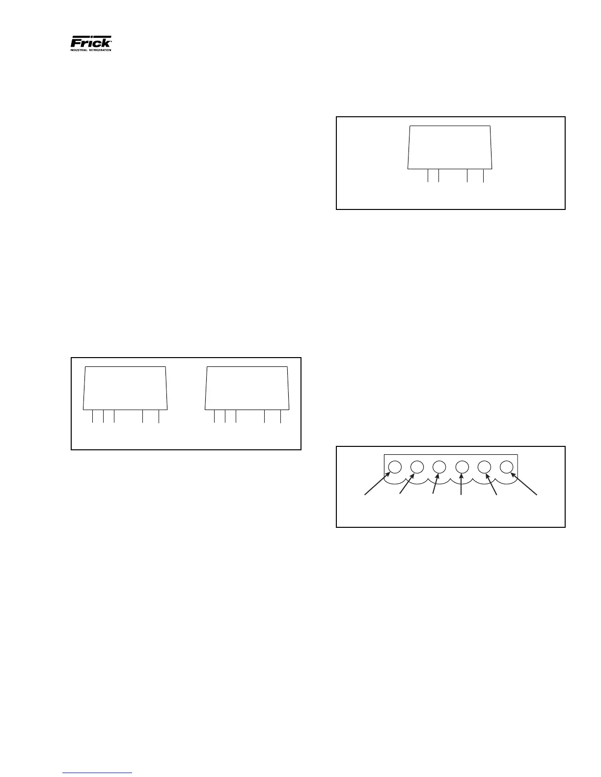
CHECKING THE DIGITAL INPUTS AND
OUTPUTS
Some problems that may be encountered involve trouble-
shooting the digital inputs and outputs. The Digital I/O (Input
/ Output) Boards have six Digital I/O (DIO) board connectors
labeled P1 through P6. The Input and Output modules are
wired to a DIO connector plug. Position 3 provides power
and position 4 is a neutral on the DIO connectors. Positions
1, 2, 5, and 6 are signal connections, as shown below:
Figure 14. Signal Connections
osition 1
Position 2
HOT NEUTRAL Position 3
Position
090.040-LD0008.eps
The Digital board’s I/O modules are congured by proper
module selection, AC or DC, operating voltage, input or
output, and moving the fuse to the in or out position. An
LED is associated with each module and displays the state
of each module. A lit LED represents an Input that is High,
receiving a signal or an Output that is On.
If a properly congured Digital I/O is not responding correctly,
rst look at the Digital Board on the Service Screen and check
if the module is on. If it is not on, check if the LED on the
Digital Board is also not lit. If the LED is not lit, then check
the fuse. If the fuse is OK, then check the module.