QUANTUM
™
HD COMPRESSOR CONTROL PANEL
MAINTENANCE
090.040-M (NOV 2016)
Page 41
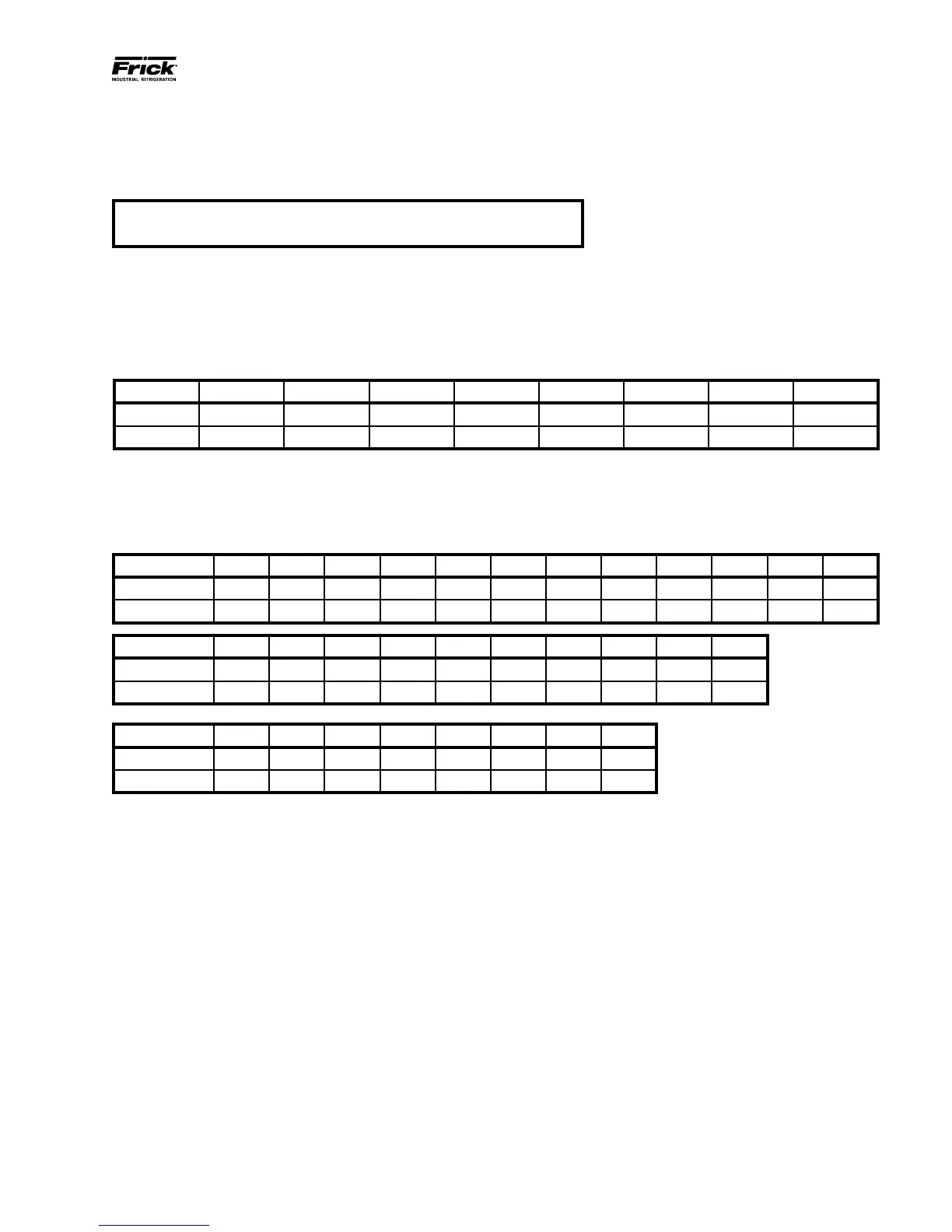
ANALOG BOARD SETTINGS
Table 12. Communications
Table 13. Dipswitch Settings (Used to set board address)
Table 14. Analog Board Jumper Settings
PINS 1-2 ARE FOR 30mA MAX SENSOR POWER (ie. ICTD, PRESSURE TRANSDUCER, PRESSURE TRANSMITTERS, LINEAR
TRANSMITTERS, ANY DEVICE THAT REQUIRES 9-28VDC POWER)
PINS 2-3 ARE FOR 3mA MAX SENSOR POWER (ie. RTD'S [PT100], ACCELEROMETERS)
The following table is to be used when con guring the Quantum HD for external communications.
J33
Pins 1-2 120 ohm long communications line termination.
Pins 2-3 * No termination.
090.040-TB0012.indd
The following table is to be used to set the analog board addresses. If there is only one board installed, it should be set as
board #1, if there are two boards they each need to be set according to the wiring diagrams.
SW1 SW2 SW3 SW4 SW5 SW6 SW7 SW8
Board #1 Off Off Off Off Off Off Off Off
Board #2 On Off Off Off Off Off Off Off
090.040-TB0013.indd
Jumpers shown are the default jumper settings per analog board. See wiring diagrams for correct jumper settings.
J1 J2 J3 J4 J5 J6 J7 J8 J9 J10 J11 J12
Analog Bd #1 1-2 1-2 1-2 1-2 1-2 1-2 1-2 1-2 1-2 1-2 1-2 1-2
Analog Bd #2 1-2 1-2 1-2 1-2 1-2 1-2 1-2 1-2 1-2 1-2 1-2 1-2
J13 J16 J17 J18 J19 J20 J21 J22 J23 J24
Analog Bd #1 1-2 1-2 2-3 2-3 2-3 2-3 2-3 2-3 2-3 2-3
Analog Bd #2 1-2 1-2 1-2 1-2 1-2 1-2 1-2 1-2 1-2 1-2
JC17 JC18 JC19 JC20 JC21 JC22 JC23 JC24
Analog Bd #1 OUT OUT OUT OUT IN IN IN IN
Analog Bd #2 IN IN IN IN IN IN IN IN
090.040-TB0014.indd