QUANTUM
™
HD COMPRESSOR CONTROL PANEL
MAINTENANCE
090.040-M (NOV 2016)
Page 109
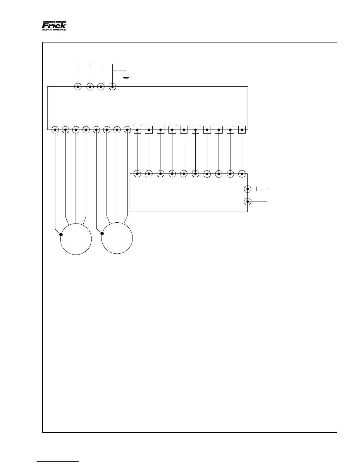
This drawing appears here for reference purposes only, and is subject to change without notice. When installing, or servicing equipment,
always refer to the actual drawings that are included with the control panel for the latest information.
GND T1 T2 T3 GND T1 T2 T3 GND 20 19 18 8 5 4 3 2 1
CONSULT STARTER AND MOTOR WIRNG DIAGRAMS
FOR EXACT WIRING CONFIGURATION
FRICK SUPPLIED COMBINATION
STARTER PACKAGE
Quantum
TM
HD
COMP
MOTOR
OIL PUMP
MOTOR
FRICK QUANTUM
TM
HD ENCLOSURE
5
25
NOTES:
1.
2.
3.
4.
5.
REFER TO MOTOR NAMEPLATE
CORRECT MOTOR CONNECTION.
SEPARATE CONDUIT RUNS
CONTROL VOLTAGE WIRING
MOTOR CONNECTION WIRING.
CONDUIT GROUNDS ARE NO
ACCEPTABLE.
ALL WIRING MUST BE PER LA
EDITION OF THE NEC AND LO
CODES.
ALL CONTROL VOLTAGE WIRING TO
BE 14 AWG STRANDED.
HI-LEVEL CUTOUT
AND/OR OTHER FIELD
SAFETY CUTOUTS AS
REQUIRED.
090.040-WD0052.eps
Figure 36. Point-To-Point Field Wiring Diagram
*(Refer to Frick publication 090.400-SB for installation guidelines)