QUANTUM
™
HD COMPRESSOR CONTROL PANEL
MAINTENANCE
090.040-M (NOV 2016)
Page 37
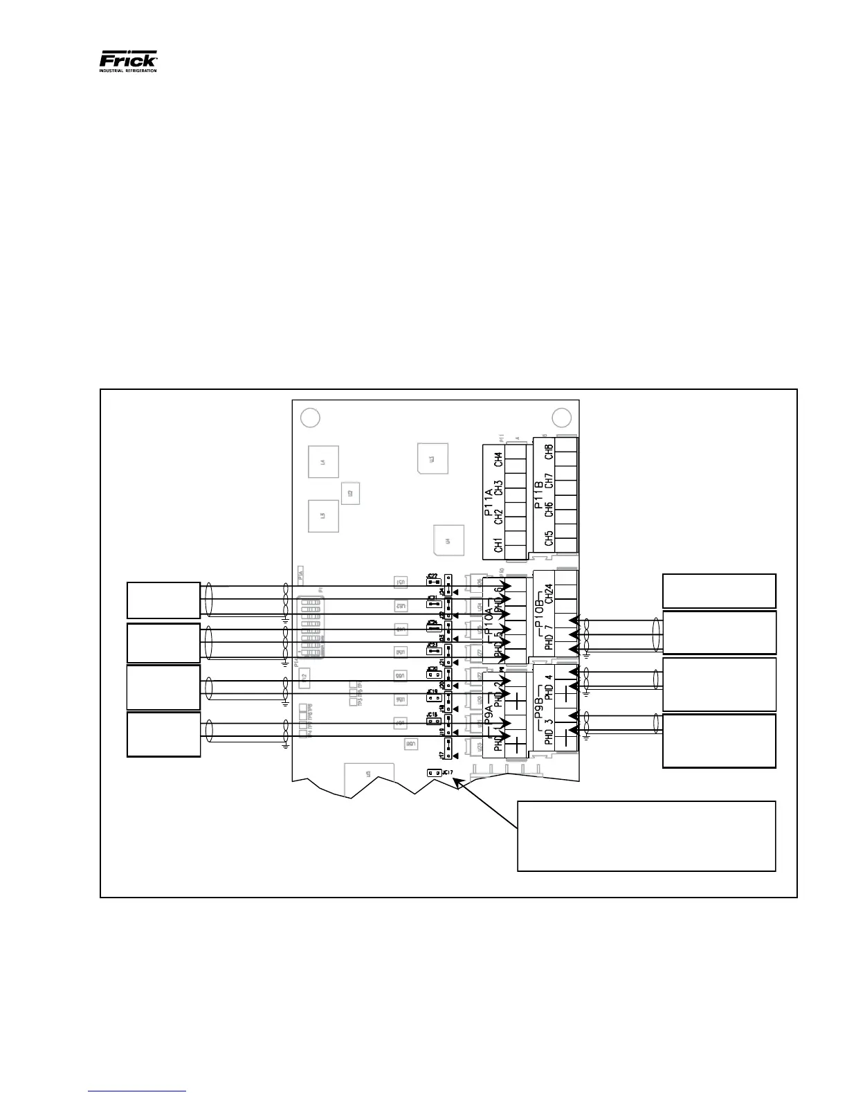
PHD VIBRATION ANALYSIS
The Frick™ 32 channel analog board has the built-in capability
to directly receive signals from vibration accelerometers,
and motor stator RTDs (100 Ω platinum) which are mounted
on the compressor housing and/or the motor/shaft. The
purpose of these devices is to monitor compressor plus
motor/bearing vibration and/or motor bearing plus motor
stator temperature.
Accelerometers transmit continuous signals to the analog
board. The Q5 Processor Board software monitors these
signals, and can detect any variations in the frequency of
the vibration. If the vibration levels increase over time,
predened setpoint limits may be exceeded, resulting in a
warning from the Quantum™ HD notifying the operator of
the condition. If the alarm is not addressed, a shutdown will
occur to prevent damage to the compressor. Likewise, if an
RTD is used for bearings, it will measure the temperature of
the motor bearings and stator, which may increase (due to
lack of lubrication).
Typically, all PHD related connections will be to Analog Board
# 1. However, if monitoring of both motor bearing vibration
and temperature is required, the temperature sensors will
be wired to Analog board #2, channels 19 and 20. Refer
to the drawing at the bottom of this page for the wiring
connections of the different possible congurations.
The full wiring diagram may be found later in this manual in
the Quantum™ HD Drawings section. Additional information
on PHD vibration monitoring and theory may be found in
the PhD Vibration Monitoring System manual (E70.020-TB).
PHD Ch. 4
Opposite Shaft Side Motor
Vibration (Accelerometer) Or
Opposite Shaft Side Motor
Temp. (RTD or Thermocouple)
Minus to Pin 6
Signal to Pin 5
PHD Ch. 3
Shaft Side Motor Vibration
(Accelerometer) Or Shaft Side
Motor Temp. (RTD or
Thermocouple)
Minus to Pin 3
Signal to Pin 2
PHD Ch. 7
Motor Stator #3 Temp. (RTD)
Minus to Pin 3
Signal to Pin 2
Plus to Pin 1
Jumpers J17-J23 installed across pins 2-3 as Default
Jumper J24 installed across pins 1-2 as Default
Jumpers JC17-JC20 not installed as Default for Accelerometers
Jumpers JC19-JC20 Installed if Motor Temperature is installed
Jumpers JC21-24 installed as Default
Analog Board Ch. 24
EZ-Cool Liquid Injection Oil
PHD Ch. 6
Motor Stator
#2 Temp. (RTD)
Minus to Pin 3
Signal to Pin 2
Plus to Pin 1
PHD Ch. 5
Motor Stator
#1 Temp. (RTD)
Minus to Pin 3
Signal to Pin 2
Plus to Pin 1
PHD Ch. 2
Discharge End
Vibration
(Accelerometer)
PHD Ch. 1
Suction End
Vibration
(Accelerometer)
Minus to Pin 3
Signal to Pin 2
Minus to Pin 3
Signal to Pin 2
090.040-WD0009.eps
Figure 19. PHD Connections (Analog Board #1)