QUANTUM
™
HD COMPRESSOR CONTROL PANEL
MAINTENANCE
090.040-M (NOV 2016)
Page 11
TOUCHSCREEN DESCRIPTION
The Quantum™ HD utilizes an 8-wire resistive touchscreen
interface to facilitate operator interaction. It consists of a
transparent sheet of glass, which covers the entire display
area, and has numerous rows and columns of micro wires
embedded into its surface. Touching anywhere on the glass
will cause an adjacent row and column of these micro wires
to sense the pressure, and signals the control electronics
that a connection has occurred, and converts the signal to
a cursor location. The action is very similar to the way a
computer mouse would be utilized, in that manipulating a
mouse moves a cursor around on the screen, but in the case
of a touchscreen, a nger tip causes the cursor to move.
The touchscreen allows the operator to simply touch active
areas of the display for the purpose of changing setpoints,
selecting menus, and accessing other operational features.
TOUCHSCREEN CALIBRATION
For the touchscreen to be used reliably, it must be accurately
calibrated. The symptom of an improperly calibrated screen
would be that an area of the screen that the user is touching
is not being recognized, or an adjacent picture element is
being activated instead of the intended one. It is also advis-
able to perform a calibration at unit commissioning.
There are two methods that may be used to access the
Calibration feature:
1. As the Quantum™ HD is powering up, a prompt will appear
for 5 seconds, allowing access to the Screen Calibration
feature.
2. After the Quantum™ HD has been booted, the Screen
Calibration feautre may be accessed by logging into the
service level, then press [Menu]. Once the Menu ap-
pears, press [Service]. After the Service screen appears,
locate the tab that is labled [Calibrate Touch Screen]
and select it.
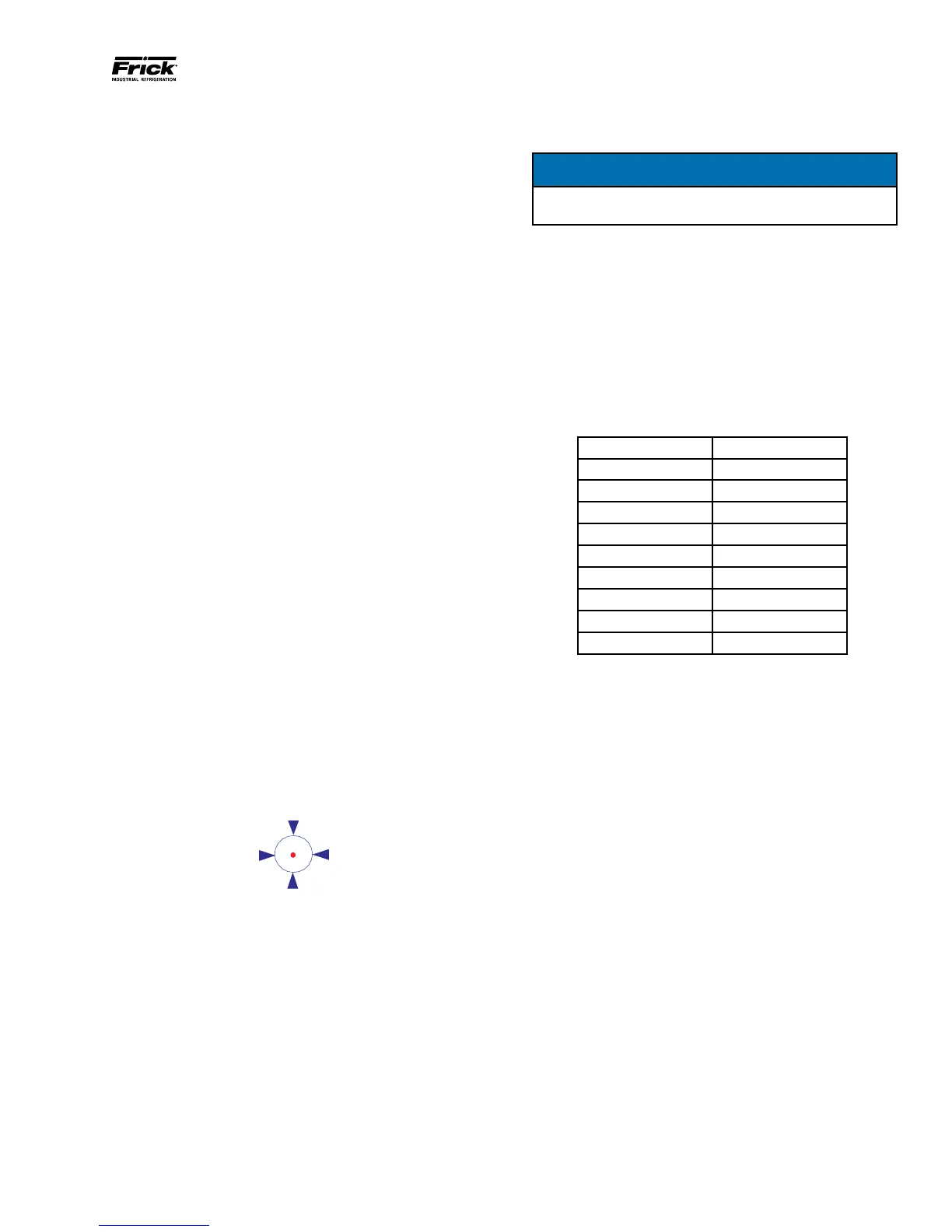
The display screen will be replaced with an all white screen.
The upper left hand corner of the screen will show a red dot
inside of an animated blue circle with arrows pointing to the
center, as shown here:
The blue circle repeatedly shrinks and grows, to call atten-
tion to the red dot inside. Press as close as possible to the
red dot. After the touchscreen has detected the depression,
the animated circle will move to its next calibration point.
Simply follow the circle, depressing at the red dot in each
new location that it moves to. There will be a total of sixteen
calibration points that will need dened. Upon successfully
dening each point, the screen will return to the home screen.
Screen calibration is complete.
USING AN EXTERNAL USB STYLE
KEYBOARD OR MOUSE
NOTICE
Always be aware of the presence of live AC voltage
within the control enclosure!
TO USE A USB COMPATIBLE COMPUTER KEYBOARD:
Open the control panel door, then use the following
instructions:
Locate the two USB connections on the Q5 Processor Board,
and plug the USB end of the keyboard cable into either one.
The external USB based keyboard is now active and ready
to use. To navigate using the external USB style keyboard
using keyboard mapping, refer to the following chart for
special functions:
Table 2. Keyboard Mapping
Keyboard Key Function
F2 Screen Calibration
F3 Stop Load
F4 Stop Unload
F5 Home
F7 Load
F8 Start Compressor
F9 Unload
F11 Alarm Silence
F12 Stop Compressor
090.040-TB0002.indd
TO USE A USB COMPATIBLE COMPUTER MOUSE:
If using a mouse, note that by moving it, the on-screen cursor
will track it’s movement. Simply navigate the cursor using
the mouse to simulate a nger tip. Click on the screen areas
that you wish to access by pressing the left hand mouse
button. Use the on-screen data and keyboard entry boxes
that appear to enter values and text.
FOR QUANTUM™ HD PANELS WITH KEYPAD
When the Quantum™ HD was rst introduced, and for sev-
eral years afterward, the front panel Touchscreen overlay
included a keypad below the display. The keypad portion of
this overlay has been eliminated in current models. In the
event that a new Touchscreen overlay would need to be
ordered, a eld replacement kit has been provided. The part
number for this kit is 649D6101G01 (SAP #1032704). This
kit comes with replacement instructions and spacers that
allow the new ovelay to be aligned properly with the cutout
opening in the panel door.