QUANTUM
™
HD COMPRESSOR CONTROL PANEL
MAINTENANCE
090.040-M (NOV 2016)
Page 36
screen. Improper setup of either the hardware or software
will result in improper operation or range.
The most common fault associated with the improper reading
of the analog channels other than hardware or software setup
problems fall into one of the following categories:
• Sensor fault
• Wiring problem
• Improper grounding of system
An open wire, shorted or shunted wire, or faulty sensor will
usually give a reading at either the minimum or maximum
end of the range scale. An erratic reading or a reading that
seems to oat up and down is usually indicative of a ground-
ing problem. When a single transducer or cable is shorted
to earth (or system) ground, this can show up as a whole
assortment of problem channels. The easiest way to nd a
short to earth problem is to disconnect all the sensor plugs
and ohm out each plug screw terminal to earth for open
(innite) impedance. All sensors should read open to earth
with the exception of the CT motor current channel. One side
of the CT is grounded in the Motor Control Center (MCC).
(The third pin on pressure sensors is ground.)
REPLACING A DEFECTIVE ANALOG BOARD
The procedure to replace an Analog board is outlined below:
1. Shut off control power.
2. Unplug all connectors from the board.
3. Remove the old board from the machine and remove the
new board from its packing and place both on an anti-
static surface.
4. Check that all jumpers and dipswitches are properly setup
on the new board as it was on the old board.
5. Install the modied replacement board in the panel.
6. Plug all connectors back in.
7. Turn on control power.
8. After replacing or installing an Analog Board and powering
on the control panel, the processor will start to communi-
cate to the new board automatically. If this does not occur
power down the panel and check the dipswitch settings.
If correct re-power the panel.
If an I/O board is removed for any reason an I/O Comms fail
message for that board will occur. It will be necessary to do
a [Redect I/O Comms] to reset the processor memory as
to which boards it is communicating to. Always check the
about screen after a Redetect to be sure that all boards are
accounted for.
ANALOG OUTPUTS
An Analog Output is the portion of the hardware that the
Quantum™ HD uses to provide control. With the Quantum™
HD, this output is typically a 4-20 mA signal that is output-
ted to an external device. This device is usually a customer
specic application, such as to simply receive a signal back
from the Quantum™ HD providing the Slide Valve Position
to an external application (perhaps a PLC), as an example.
The output can be set as a 0-20mA signal in the calibration
of the output by accessing Menu > Calibration > Output.
The 4-20mA signal can be altered if necessary to a Vdc signal
by using a resistor at the input of the device being controlled.
Refer to the following chart for values:
Original
signal
Desired
signal
Resistor to use
4-20mA 1-5Vdc 250 ohm, 1%, 1/4 watt
4-20mA 2-10Vdc 500 ohm, 1%, 1/2 watt
0-20mA 0-5Vdc 250 ohm, 1%, 1/4 watt
0-20mA 0-10Vdc 500 ohm, 1%, 1/2 watt
090.040-TB0011.indd
Table 11. Resistor Values
TROUBLESHOOTING THE
ANALOG INPUTS AND OUTPUTS
Some problems that are encountered involve troubleshoot-
ing the Analog inputs and outputs. The Analog Board has
twelve Analog I/O board connectors labeled P4 through P10.
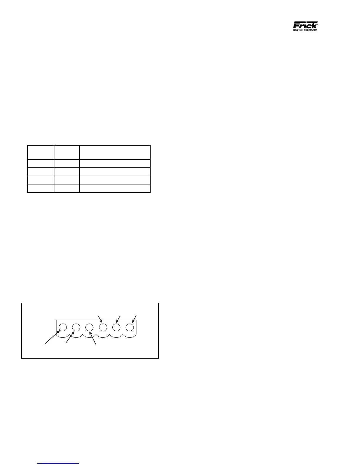
The external Analog devices are wired to a connector plug.
Position 1 connects to the plus (+) of the external device
for channel 1, position 2 connects to the signal (SIG) of the
external device for channel 1 and position 3 connects to
ground (GND) of the external device for channel 1. Position 4
connects to the plus (+) of the external device for channel 2,
position 5 connects to the signal (SIG) of the external device
for channel 2 and position 6 connects to ground (GND) of the
external device for channel 2, as shown below:
Figure 18. Signal Connections
Channel 1
+ Power
Signal
Channel 1
GND
GND
090.040-LD0010.eps
Each channel is setup through software calibration for the
proper transducer type and range, and each transducer must
be calibrated through the appropriate sensor calibration