QUANTUM
™
HD COMPRESSOR CONTROL PANEL
MAINTENANCE
090.040-M (NOV 2016)
Page 35
• A problem may exist with one of the I/O boards (Digital
or Analog).
• If the power LED is not lighted, check the cable for proper
connectivity.
ACTIVE LED
The Analog Board has an Active LED indicator that blinks
when the board’s software is running.
If the Active LED is not blinking, it could be an indication
that the internal program is not running. Try powering the
Q5 Processor Board off, then back on to see if the Active
light starts blinking. If not, a new board may be required.
ANALOG INPUTS
An Analog Input is the portion of the hardware that allows
devices such as temperature sensors and pressure trans-
ducers to interface with the Quantum™ HD. The software
program within the Quantum™ HD is constantly looking at
these Input channels, via communications, and based upon
what the voltage or current level of the channel is, will pro-
vide the necessary control for an associated action.
Analog inputs arrive at the board on connectors P4 through
P10. Each of these connectors can receive two channels (for
a total of twenty-four).
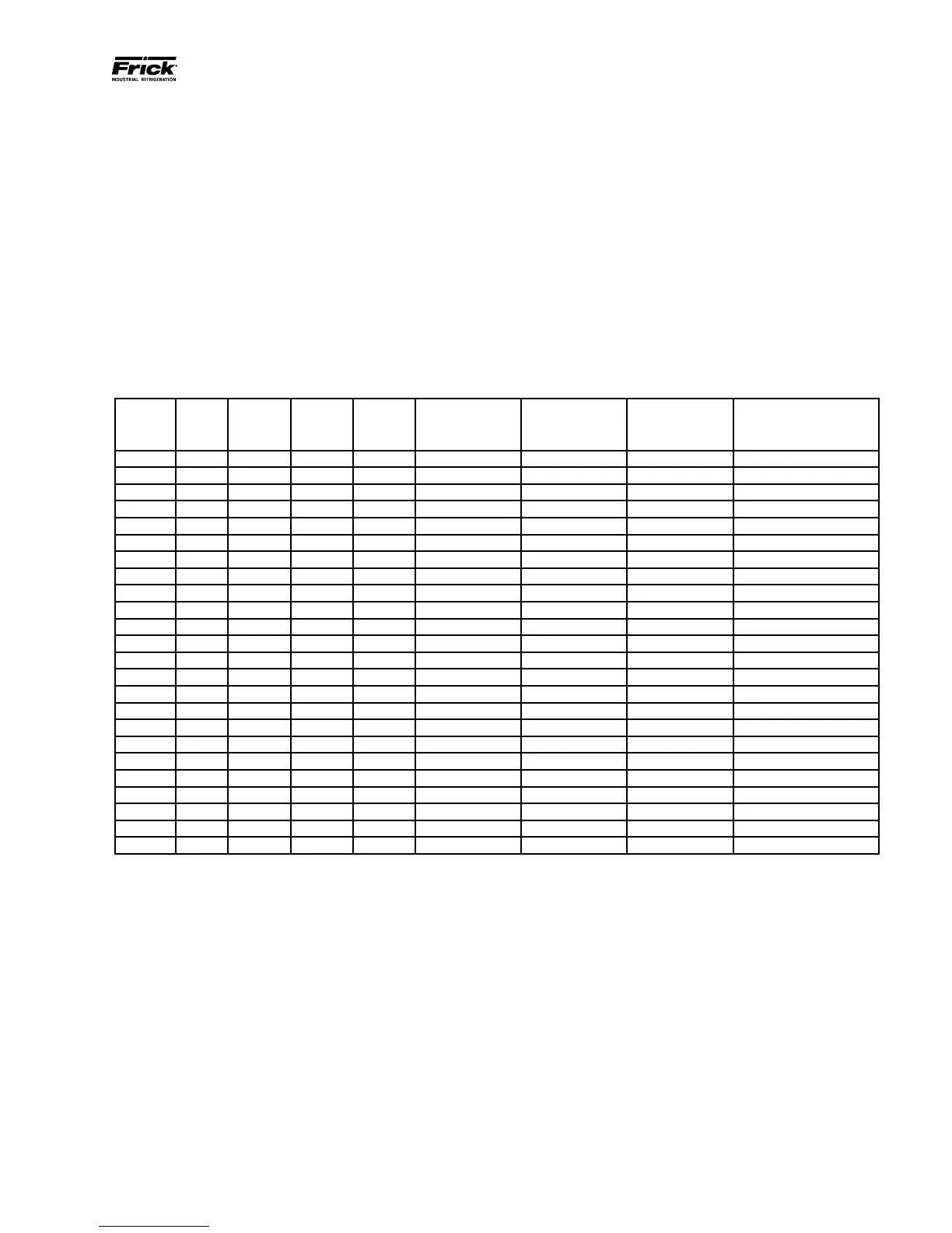
Refer to the following chart for a listing of possible input
channel congurations.
ANALOG BOARD INPUT CONFIGURATION TABLE
Channel ICTD 0-5Vdc 0-10Vdc 0-20mA
POT
(Potentiometer)
CT
(Motor Current)
Accelerometer
(Vibration
Monitoring)
RTD
(Motor
Protection Only)
1 * * * * *
2 * * * * *
3 * * * * *
4 * * * * *
5 * * * * *
6 * * * * *
7 * * * * *
8 * * * * *
9 * * * * *
10 * * * * *
11 * * * * *
12 * * * * *
13 * * * * *
14 * * * * *
15 * * * * *
16 * * * * * *
17 * * * * * *
18 * * * * * *
19 * * * * * *
20 * * * * * *
21 * * * * * *
22 * * * * * *
23 * * * * * *
24 * * * * * *
090.040-TB0010.indd
Table 10. Analog Board Input Conguration Table