QUANTUM
™
HD COMPRESSOR CONTROL PANEL
MAINTENANCE
090.040-M (NOV 2016)
Page 108
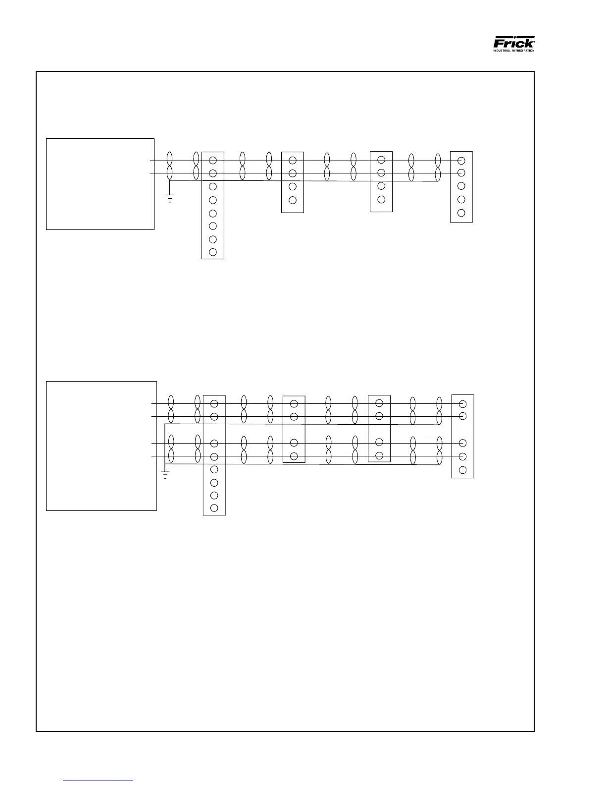
This drawing appears here for reference purposes only, and is subject to change without notice. When installing, or servicing equipment,
always refer to the actual drawings that are included with the control panel for the latest information.
Figure 35. Communications Wiring Diagrams
TO CUSTOMER REMOTE COMPUTER/DCS
RS-485 COMMUNICATIONS
TO CUSTOMER REMOTE COMPUTER/DCS
RS-422 COMMUNICATIONS
C
-RX/-TX
+RX/+TX
1
2
3
4
5
6
7
8
1
2
3
4
1
2
3
4
5
1
2
3
4
COMPRESSOR #2
Q3 or Q4
COM-2 (TB2)
COMPRESSOR #4
Q5
COM-2 (P11)
BLK
CLR
BLK
CLR
COMPRESSOR #1
Q1 or Q2
COM-2 (P12)
COMPRESSOR #3
Q3 or Q4
COM-2 (TB2)
BLK
CLR
BLK
CLR
-RX/-TX
+RX/+TX
To Customer
Remote
Computer /
DCS System
- Cable -
Belden #9841
#24 AWG or Equal
1
2
3
4
5
6
7
8
5
4
9
8
BLK
GRN
BLK
RED
BLK
GRN
BLK
RED
BLK
GRN
BLK
RED
COMPRESSOR #3
COMPRESSOR #2
RWBII/RDB/RXB/RXF
PLUS PANEL
Q1 or Q2
COM-2 (P12)
BLK
GRN
BLK
RED
-TX
+TX
To Customer
Remote
Computer /
DCS System
- Cable -
Belden #9841
#24 AWG or Equal
-RX
+RX
COMPRESSOR #4
Q5
COM-2 (P11)
1
2
3
4
5
-RX
+RX
-TX
+TX
Q3 or Q4
COM-2 (TB2)
1
2
3
4
090.040-WD0053.eps
(RS-485 & RS-422)