QUANTUM
™
HD COMPRESSOR CONTROL PANEL
MAINTENANCE
090.040-M (NOV 2016)
Page 22
DESCRIPTION
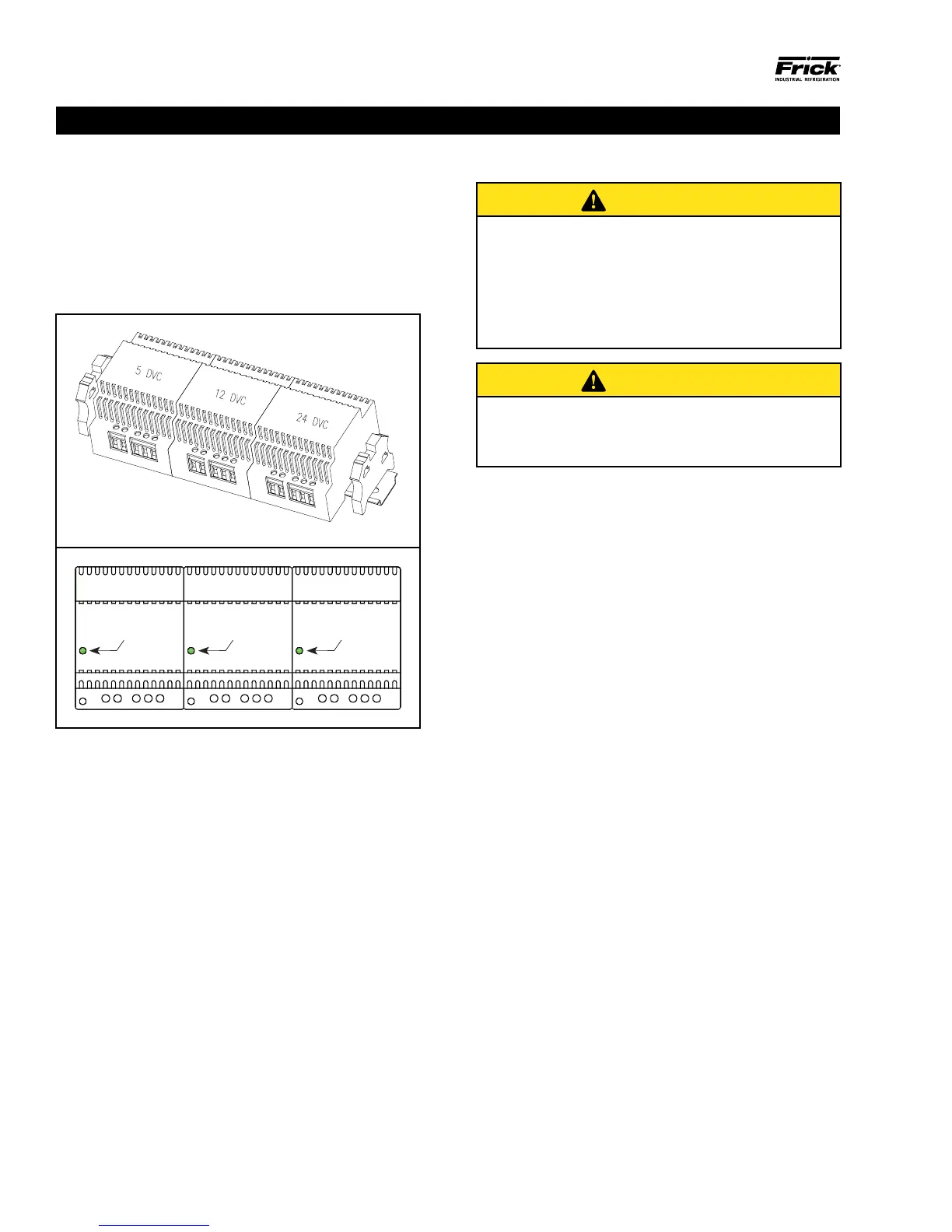
The power supply of the HD control panel consists of three
independent supplies, and are located on the inside of
the front door below the Interface board. They supply the
following DC voltages:
• +5 VDC Output 5A / 25W
• +12 VDC Output 4A / 48W
• +24 VDC Output 2A / 48W
090.040-LD0002.eps
Figure 9. Power Supplies
+5 VDC
Power LED
+12 VDC
Power LED
+24 VDC
Power LED
Output 5A / 25W Output 4A / 48W Output 2A / 48W
090.040-LD0003.eps
All three supplies are adjustable and each has a green
LED indicator to show that they are powered. Refer to the
following page for the location for the adjustment.
POWER DISTRIBUTION
DC power from the power supplies is wired directly to a
series of terminal blocks. The terminals for these voltages
are labeled as follows:
• Common (1000)
• +24 VDC (1004)
• +5 VDC (1001)
• +12 VDC (1002)
+12 VDC power is then distributed to the Q5 Processor
Board, Interface Board. +5 VDC is for the Digital board(s),
and +24 VDC is for external as needed control.
+24 VDC is used to power the 614 analog boards and other
external devices. Total load on this supply cannot exceed
2A / 48W.
+12 VDC is used to power the display, processor and interface
boards. Total load on this supply cannot exceed 4A / 48W.
+5 VDC is used to power the digital boards. Total load on
the supply cannot exceed 5A / 25W.
MEASURING VOLTAGES
CAUTION
Measuring and adjusting the power supply voltages
require the control power switch to be energized.
Extreme care must be observed when taking any
readings, as 120 or 230 VAC (depending on incoming
system voltage) will be present next to the DC voltage
connector. Adjusting the supplies requires the use of a
small insulated Philips screwdriver inserted into the
supply to access an adjusting potentiometer.
CAUTION
It is possible for the screwdriver (and the person
making the adjustment) to come into contact with
potentially lethal voltages. Proper Personal Protective
Equipment (PPE) measures need to be observed.
All circuit boards within the Quantum HD control panel require
accurately adjusted DC voltages to function properly. Periodic
measurement and adjustment of the DC power system is
recommended for optimum system operation. Over time, it is
possible for temperature, humidity, vibration and component
age, to degrade the accuracy of these voltages. When any
of the DC voltages begin to stray from their optimum range,
mysterious problems can begin to arise.
Even with a perfectly adjusted supply, it is possible for a
potential drop in voltage at each connection point. This drop
normally is in the millivolt range, but under some conditions,
the drop can be much greater (as high as tenths of a volt). By
the time the voltage reaches the last board in the daisy chain,
and all of these potential voltage drops are considered, the
combined drop can be such that problems can be apparent.
Some examples of problems could be:
• Loss of or intermittent communications failures.
• A shutdown message stating Digital Board x Reset (where
“x” is replaced by the number of the Digital Board that failed).
• An shutdown message stating Analog Board x Comm. Fail
- Shutdown (where “x” is replaced by the number of the
Analog Board that failed).
• Numerous sensor fault shutdown messages.
• Q5 Processor Board reboots for no apparent reason.
• Improper readings of analog pressures and temperatures.
• LED's on the Q5 Processor Board are lit, but nothing
appears on the display.
To perform measurements and adjustments on the power
supply voltages, use a reliable, calibrated Digital Volt Meter
(DVM). The DVM should be accurate to 1/100 of a volt DC.
With the control power switch turned ON, wait until the
Operating Screen appears. This is because the graphics
required to create this screen will draw more current than
when the screen is not fully booted. If the screen never ap-
pears however (possibly due to a voltage problem), you will
need to proceed regardless of what is or is not displayed.
POWER SUPPLY