QUANTUM
™
HD COMPRESSOR CONTROL PANEL
MAINTENANCE
090.040-M (NOV 2016)
Page 26
INFORMATION
The information that follows in this section can help locate
problems that can occur with Digital Input and Output circuit
boards.
DIGITAL BOARD DESCRIPTION
The Digital board is a small microprocessor board and is
programmed to control discrete outputs, or accept discrete
inputs, from external electrical devices. Each Digital board
has the capability of 24 independent channels or I/O (Input/
Output). Each channel that is used needs a module plugged
into it. A yellow module indicates that it is used for Inputs. A
black module is used for Outputs. The standard Quantum™
HD compressor control can have up to two Digital boards
(depending on options).
COMMUNICATIONS LED'S
The Q5 Processor Board is in constant communication with
all Digital (and Analog) Boards. You will notice on each Digital
and Analog board, there are a pair of LED's labeled as RX and
TX. These letters represent Receive (RX) and Transmit (TX).
These LED's should be ashing at a high rate during normal
operation. This indicates that the Q5 Processor Board, and
the Digital board are properly communicating with each other.
• Reference the JUMPER AND DIPSWITCH SETTINGS section
later in this manual. This section contains the dipswitch
settings for addressing the Digital I/O boards. When these
switches are properly set, the main board is able to serially
communicate with each I/O board and provide control sig-
nals and data exchange. If these switches are not properly
set, the result will be lost or failed communications, or
the wrong outputs being energized, or the wrong inputs
being received.
CONNECTIONS TO THE QUANTUM™ HD
As stated earlier, the Quantum™ HD standard compressor
control system utilizes up to two Digital, and two Analog
boards. To connect these boards together so that the Quan-
tum™ HD can control them, they must be connected with a
wiring harness that provides all of the necessary D.C. voltage
requirements, as well as the communications capabilities.
The Digital boards only require the +5 Vdc voltage and the
Return (or common) for logic power. The communications
signals (RX & TX) are required by all boards.
A harness distributes power and communications from the
terminal blocks to the various logic boards. The harness splits
into two branches, each ends with two 16 pin connectors.
The branch that supplies power and communications to the
Digital board(s) utilizes red and black wires for +5Vdc power
and Common, and white/black and white/red wires for serial
communications.
LOGIC VOLTAGE (POWER) LED
Located on the Digital Board is a Power LED. This LED will be
illuminated as long as the Control Power switch is ON, and
the proper voltage is present at the power supply. The power
supply generates the +5 Vdc voltage and passes it on through
the Power-I/O harness. This LED does not indicate however
that the proper voltage is necessarily present at the board,
only that the voltage is enough to energize the voltage sens-
ing circuitry. If a voltage related problem is suspected with
regard to a Digital Board, the only way to actually determine
this is to read the voltage on a Digital Voltage Meter (DVM).
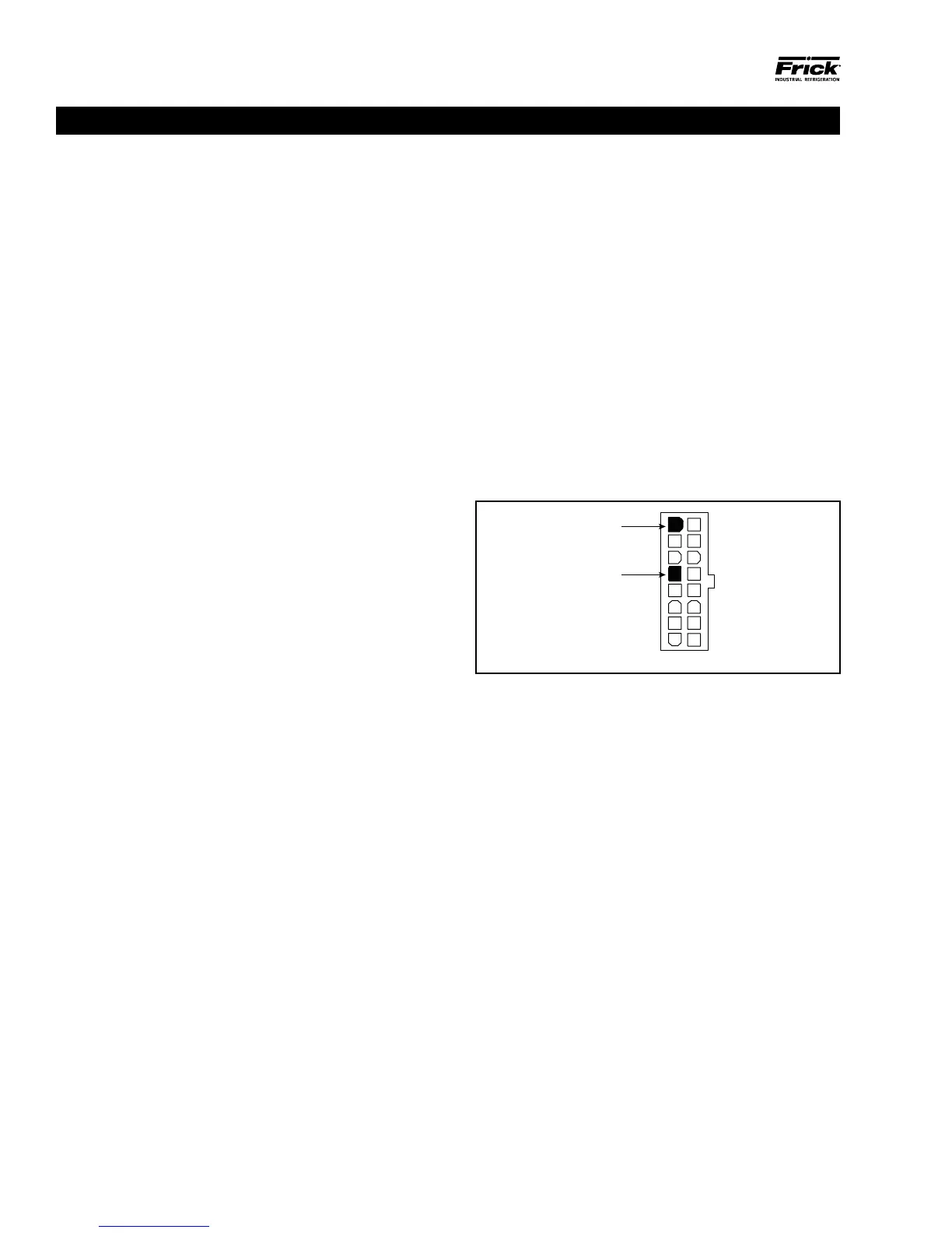
This may be accomplished by locating the white power /
communications connector on the board. Notice that the
Digital Board has one of these connectors on both ends of
the board. The associated power / communications harness
will only be plugged into one of these connectors. Take the
red (positive) probe of the DVM and carefully insert the end
into the "+5V" lead, and the black (negative) probe end into
the "RET" (Return or Common) lead, as shown below:
Figure 11. Return Lead
+5V
RET
Red
Black
090.040-LD0005.eps
Set the DVM to read DC, and set the proper range. The volt-
age reading must read a minimum of +5.0 Vdc. The Power-I/O
harness will have an associated voltage drop at each board
connection. As an example, if you are reading 5.20 Vdc at
the rst I/O board in the daisy chain, the voltage at the sub-
sequent connections for the remaining boards may be lower.
The voltage will need to be corrected for proper operation
of the system. The cause for a low voltage reading could be:
• The power supply may need adjustment (see the section
on power supplies).
• The Power-I/O communications harness has a problem (a
new harness may be needed).
• A problem may exist with one of the I/O boards (Digital
or Analog).
• If the power LED is not lighted, check the cable for proper
connectivity. Note: Each board provides the necessary
connections to feed all signals to the following connectors.
If the auxiliary Analog or Digital Board is not present then
a jumper plug (see Recommended Spare Parts List) must
be installed to daisy chain the signals.
The most common symptom that is exhibited by a low +5
Vdc voltage to the Digital Boards is an alarm message that
reads Digital Board Reset Shutdown.
DIGITAL BOARD