QUANTUM
™
HD COMPRESSOR CONTROL PANEL
MAINTENANCE
090.040-M (NOV 2016)
Page 18
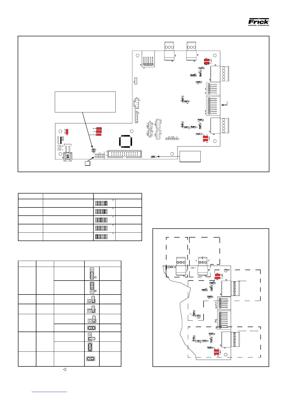
Jumper JP1 Function Jumper Setting
1 - 2 Not Used
Not Installed
3 - 4 Reformat E2Prom Installed
5 - 6 Erase Setpoints (at boot-up) Installed
7 - 8 Not Used Not Installed
9 - 10 Disable Watchdog Installed
090.040-TB0006.indd
(Comms 3 and 4 have no jumpers)
Comm 1 Comm 2 Function Jumper Setting
J1 J7
RS-422 (4-Wire)
Default
1 - 2 Closed
RS-485 (2-Wire) 2 - 3 Closed
J2 J13 Pull Down Default 1 Pin Only
J3 J16 Pull Up Default 1 Pin Only
J5 J17
RS-422 Default 1 Pin Only
RS-485 1 - 2 Closed
J6 J18
RS-422 Default 1 Pin Only
RS-485 1 - 2 Closed
J4 J22
High Speed Target
Default
1 - 2 Closed
NOTE: The triangle symbol (
) denotes Pin 1 on connectors.
3
2
1
090.040-TB0007.indd
Do Not
Remove J14
Touch-
screen
connecto
P1
Baud Rate Jumpers
J15 Not Installed = 19200 (Default)
J15 Pins 1-2 Installed = 38400
J15 Pins 3-4 Installed = 56K
J15 Pins 1-2 and 3-4 Installed = 115K
COMM
4
COMM
3
COMM
2
COMM
1
JP1
090.040-WD0002.eps
Figure 5. Interface Board Diagram
COMMS 1-4 PINOUTS AND JUMPER LOCATIONS
COMM-1
(P10)
RS-422
GND
+TX
-TX
+RX
-RX
RS-485
GND
N/C
N/C
+TX/+RX
-TX/-RX
COMM-2
(P11)
RS-422
GND
+TX
-TX
+RX
-RX
RS-485
GND
N/C
N/C
+TX/+RX
-TX/-RX
COMM-4
(P17)
RS-485
(RESERVED)
COMM-3
(P16)
RS-485
GND
+TX/+RX
-TX/-RX
090.040-WD0003.eps
Figure 6. Pinouts and Jumper Locations
Table 6. JP1 System Settings
Table 7. Comms 1 & 2 Jumper Settings