QUANTUM
™
HD COMPRESSOR CONTROL PANEL
MAINTENANCE
090.040-M (NOV 2016)
Page 34
OVERVIEW
The Frick Quantum™ HD control panel is capable of reading
external analog devices, such as temperature probes and
pressure sensors. It uses these input signals for the purpose
of monitoring and control. As an example, if an external
temperature sensor began to read a higher than expected
temperature in some area, the controller would sense this
change, and provide the necessary output control signal to
remedy the situation. Unlike a digital signal, which is typically
either an on or off state, an analog signal can assume a wide
variety of states, such as a temperatures probe reading a
wide range of temperatures.
The method used for receiving (and sending) these signals
is the analog board. The analog devices are wired directly to
the board, and the on-board software/hardware converts
the electrical signals received from these devices into data,
which is then sent on to the Q5 Processor Board via
communications.
It features twenty-four input channels, and eight output chan-
nels. Rather than using physical jumpers to congure each
channel, this is done through the software. A more detailed
description of the operation of this board is provided in the
sections that follow.
ANALOG BOARD DESCRIPTION
The Analog Board is actually a small microprocessor board
and is programmed to control analog outputs, or accept
analog inputs, from external electrical devices. Each board
has the capability of 24 independent input channels. With the
Quantum™ HD Compressor Control, these I/O channels are
dedicated through the software and external wiring, as to
the function of each channel. The Quantum™ HD 5 controller
can utilize up to two separate analog boards (Analog Board
#1 and #2), depending on the selected options.
For each of the boards that are installed, they will have
specic I/O (Input / Output) functions. For the operating
software to distinguish board #1 from #2, each board must
be properly addressed as #1 and #2 using the dipswitches
on each board (see Analog Board Dipswitch Settings chart
for this information).
COMMUNICATIONS LED’S
The main board is in constant communication with all Ana-
log (and Digital) Boards. You will notice on each Digital and
Analog board, that there are a pair of LED’s labeled as RX
and TX. These letters represent Receive (RX) and Transmit
(TX). These LED’s should be ashing at a high rate during
normal operation. This indicates that the main board, and
the Digital board that you are looking at, are properly com-
municating with each other.
• Refer to the JUMPER AND DIPSWITCH SETTINGS section
later in this section. This table contains the dipswitch set-
tings for addressing the Analog I/O boards. When these
switches are properly set, the main board is able to serially
communicate with each I/O board and provide control sig-
nals and data exchange. If these switches are not properly
set, the result will be lost or failed communications, or
the wrong outputs being energized, or the wrong inputs
being received.
CONNECTIONS TO THE QUANTUM™ HD
As stated earlier, the Quantum™ HD compressor control
system utilizes up to two Digital, and two Analog boards. To
connect these boards together so that the Quantum™ HD
can control them, they must be interconnected with a wir-
ing harness that provides all of the necessary D.C. voltage
requirements, as well as the communications capabilities.
Analog boards only require the +24Vdc voltage and the
Return (or common) for logic power. The communications
signals (RX & TX) are required by all boards.
A harness distributes power and communications from the
terminal blocks to the various logic boards. The harness splits
into two branches, with each branch ending with a 16 pin
connector. The branch that supplies power and communica-
tions to the Analog board(s) utilizes gray and black wires for
+24Vdc power and Common, and white/black and white/red
wires for serial communications.
LOGIC VOLTAGE (POWER) LED’S
Located on the Analog Board are two power LED’s. The rst
of these is D65 PG LED (+24Vdc), and will be illuminated
as long as the Control Power switch is ON, and the proper
+24Vdc voltage is present at Analog Board connector P3. This
LED does not indicate that the proper voltage is necessarily
present at the board, only that the voltage is enough to
energize the voltage sensing circuitry.
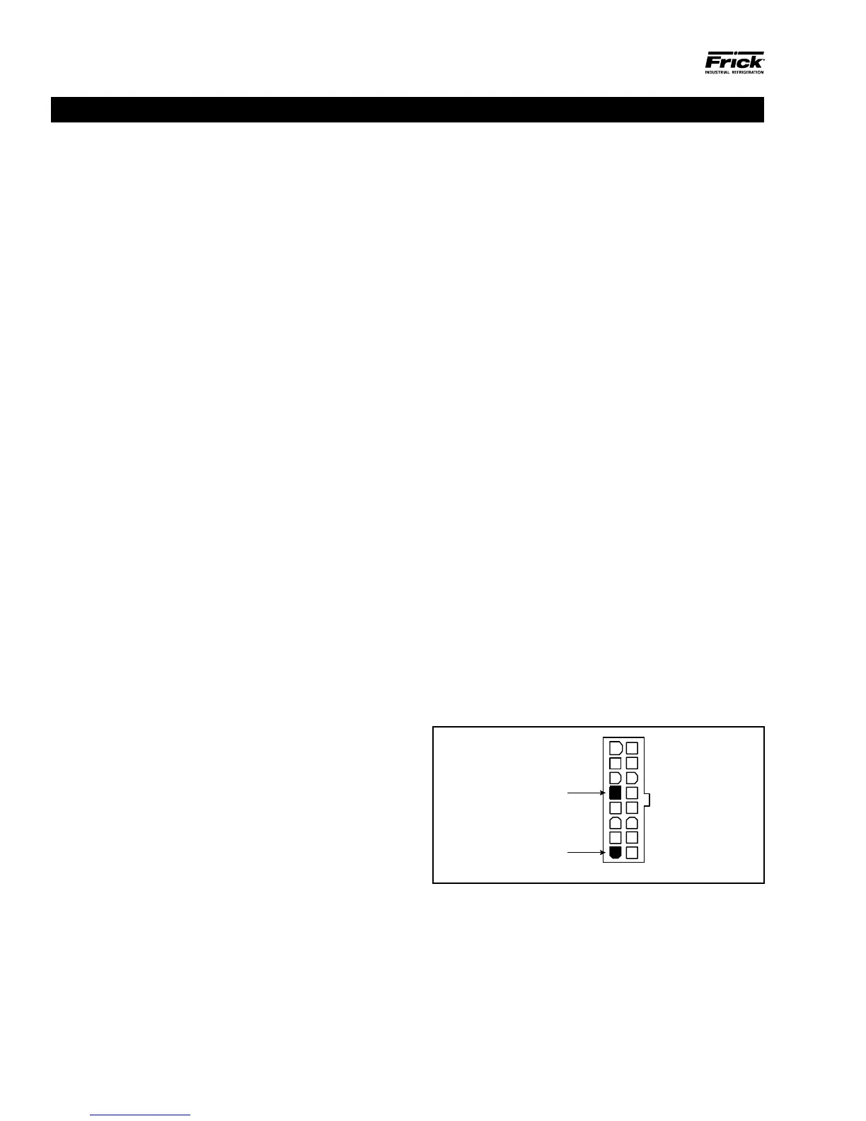
If a voltage related problem is suspected with regard to a
Board, the best way to actually determine this is to read
the voltage on a DVM (Digital Volt Meter). This may be ac-
complished by locating the white power / communications
connector on the board. Notice that the Analog Board has
only one of these connectors. The associated power/com-
munications harness plugs in to it. Take the red (positive)
probe of the DVM and carefully insert the end into the +24Vdc
lead, and the black (negative) probe end into the RET (Return
or Common) lead, as shown below:
Figure 17. Return Lead
090.040-LD0009.eps
Set the DVM to read DC, and set the proper range. The Ideal
voltage setting for the +24Vdc power is 24.2 - 24.5Vdc.
The cause for a low voltage reading could be:
• The power supply may need adjustment (see the section
on power supplies).
• The Power-I/O communications harness has a problem (a
new harness may be needed).
ANALOG BOARD