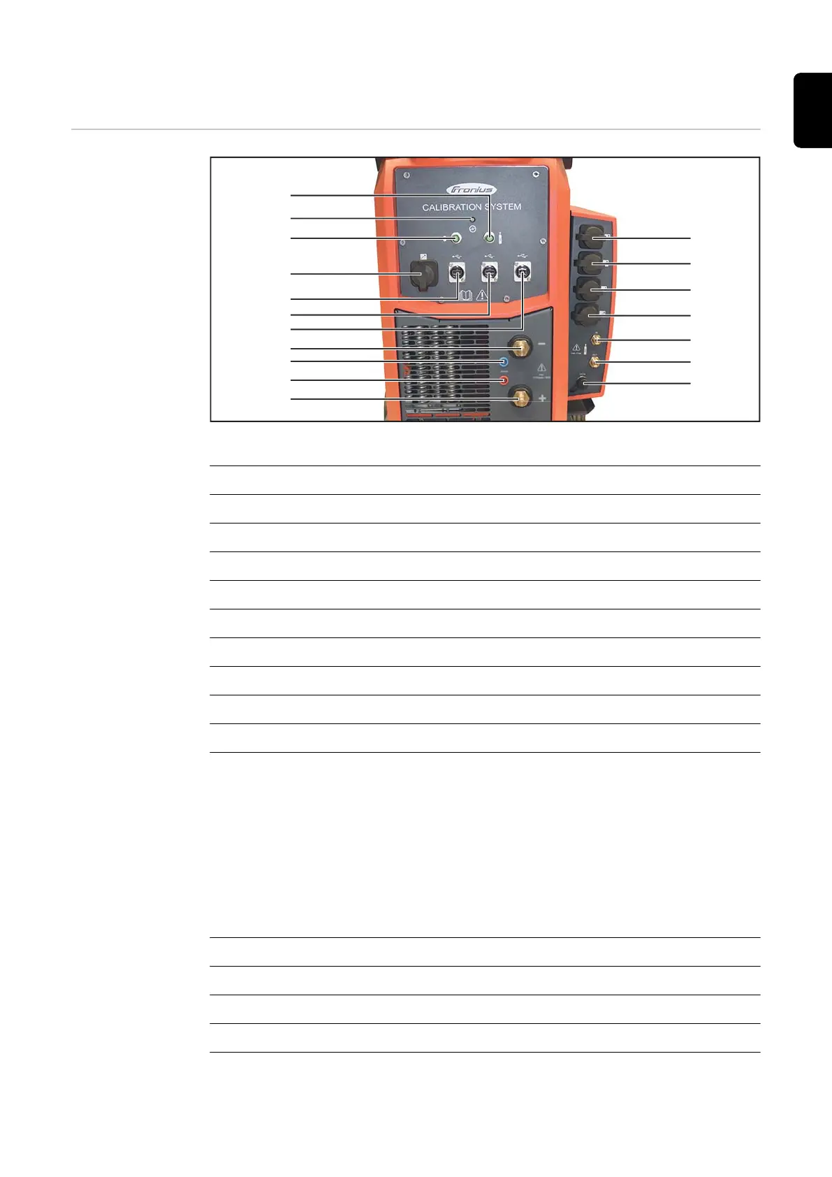
Controls and connections on calibration system
Front of device
(1)
(2)
(3)
(4)
(5)
(6)
(7)
(18)
(17)
(16)
(15)
(14)
(13)
(12)
(11)
(10)
(8)
(9)
Calibration system 2.0 with interface calibration system
Item Description
(1) (+) power connection (red)
(2) (+) sense lead connection socket (red)
(3) (-) sense lead connection socket (blue)
(4) (-) power connection (blue)
(5) USB port computer/laptop
(6) USB port for adapter
(7) USB port for adapter
(8) SpeedNet connection socket
(9) Welding wire calibration system connection socket
(10) Status indicator
Lights up green
Device is ready
Lights up red
An error has occurred
A description of the error is displayed by the software during the calibra-
tion process.
(11) Gas calibration system connection socket
(12) SpeedNet connection socket
(13) SpeedNet connection socket
(14) SpeedNet connection socket
(15) SpeedNet connection socket
25
EN