Connecting the
welding wire cal-
ibration system
NOTE!
The power cables are not relevant for calibration of the welding wire!
Establish data communication between the following:
▶
power source and calibration system (LocalNet, SpeedNet, USB, etc.)
▶
power source and wirefeeder (LocalNet, SpeedNet, USB, etc.)
▶
welding wire calibration system and calibration system
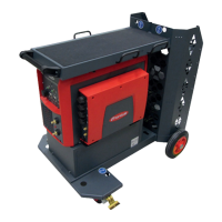
1
Connect the connection cable to
the welding wire calibration system
IMPORTANT! A maximum of 3
connection cables (max. 15 m) can
be used to connect the welding
wire calibration system and the cal-
ibration system!
2
Connect the connection cable to
the calibration system
3
(+) Disconnect power cable from
welding system
4
Connect the welding torch to the
welding system
5
Remove the gas nozzle from the
welding torch
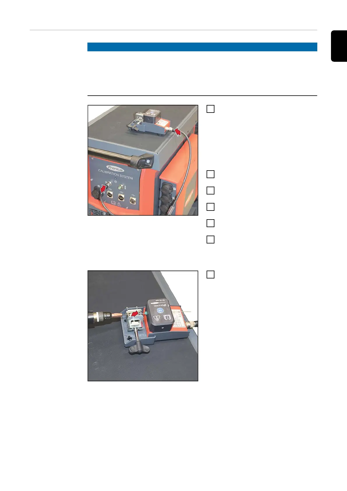
6
Thread the wire
The welding wire should protrude
approx. 200 mm from the contact
tip.
7
Thread the welding wire into the in-
take part of the sensor
45
EN