Calibrating WeldCube Connector
Overview WeldCube Connector with current/voltage measurement:
-
WeldCube Connector U/I
-
WeldCube Connector Advanced
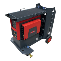
A TPS 500i power source is used when calibrating the WeldCube Connector.
System layout as shown in the figure on page 83 with the following exceptions:
-
no wirefeeder
-
no WCC Euro wire sensor
-
no Euro/central connector adapter with Tuchel socket
-
the (+) power cable from the calibration system is connected directly to the
(+) current socket on the power source.
WeldCube Connector with current/voltage measurement and wire speed meas-
urement (Euro):
-
WeldCube Connector U/I/WFS Euro
-
WeldCube Connector Advanced + OPT/WCC Wire Sensor EUR
The WeldCube Connector is calibrated using a
TPS 500i power source + WF 25i / 30i with Euro connection
or
TPS 500i power source + WF 25i / 30i + adapter ZA FSC-S-G/Euro STD
WeldCube Connector with current/voltage measurement and wire speed meas-
urement (TSt c, VR 5000):
-
WeldCube Connector U/I/WFS WSM
-
WeldCube Connector Advanced + OPT/WCC Wire Sensor WSM
The WeldCube Connector is calibrated with the existing TransSteel system com-
ponents.
System layout as shown in the figure on page 83 with the following exceptions:
-
TSt + VR 5000 instead of TPS 500i + WF 25i / 30i
or
TSt c with integrated wire drive
-
no WCC Euro wire sensor, wire sensor installed in VR 5000 or in TSt c
-
no Euro/central connector adapter with Tuchel socket
Connecting the
TPS /i power
source, Weld-
Cube Connector
and calibration
system
1
Plug the mains cable into the calibration system
2
Plug the mains cable into the grid
3
Switch on the mains switch
82