+
+
+
TPS 500i
WCC
CALSYS
WF 15i / 25i / 30i Euro
*
+
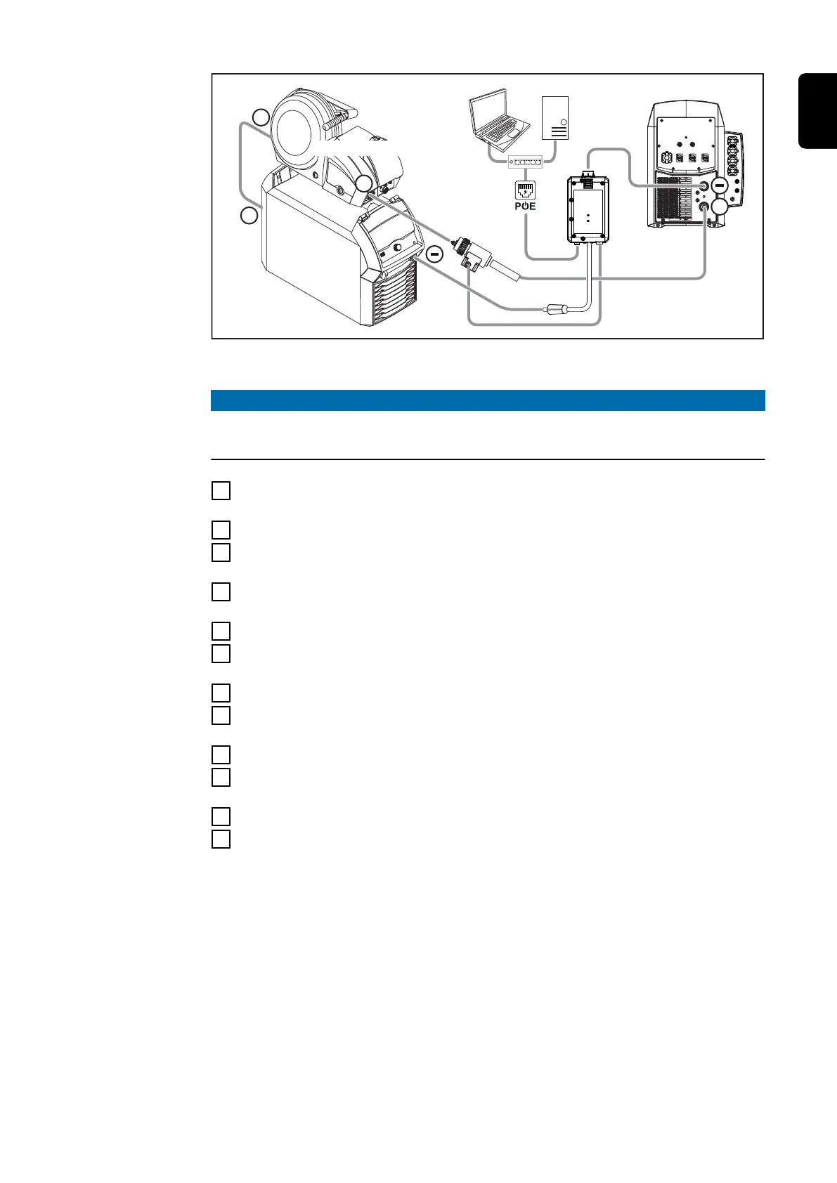
CALSYS = calibration system 2.0, WCC = WeldCube Connector, PoE = Power over Ethernet
* = Euro/central connector adapter with Tuchel socket
NOTE!
If there is a power connector for the high current socket on the power source,
use the adapter for the high current sockets to bayonet (42,0001,4482).
4
Connect the wirefeeder to the (+) socket on the power source (for example,
using the interconnecting hosepack power cable)
5
Connect the WCC Euro wire sensor to the wirefeeder
6
Connect the Euro/central connector with Tuchel socket to the WCC Euro
wire sensor
7
Connect the (+) power cable to the calibration system and the Euro/central
connector adapter with Tuchel socket
8
Connect the sense lead (red) to the calibration system
9
Connect the (-) power cable to the calibration system and the WeldCube
Connector
10
Connect the sense lead (blue) to the calibration system
11
Connect the WeldCube Connector grounding cable to the (-) socket on the
power source
12
Connect the WCC Euro wire sensor to the WeldCube Connector
13
Connect the laptop, WeldCube Premium Server and PoE to the WeldCube
Connector
14
Switch on the power source
15
Connect the SpeedNet cable to the calibration system and to a free Speed-
Net connection socket on the welding system
83
EN