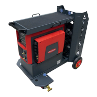
8
Secure the welding torch in the
welding wire calibration system at
the contact tip
9
Make sure that the torch hosepack
is arranged as straight as possible
NOTE!
When calibrating robot welding systems, the welding wire calibration system is
usually attached to the contact tip of the robot welding torch.
If, in this case, it is not possible to attach it properly, the following longer contact
tips may be used on the robot welding torch:
-
42,0001,0056
contact tip 1.6/M6/ø8x33 mm
-
42,0001,3485
contact tip 1.6/M8/ø8x35 mm/CB4.8
-
42,0001,5413
contact tip 3.2/M10/ø10x40 mm
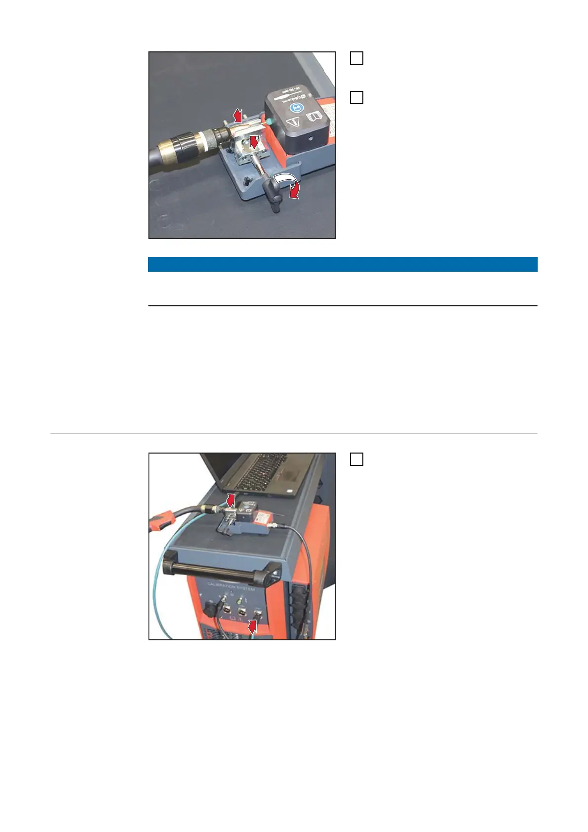
Connecting the
computer to the
calibration sys-
tem and signa-
ture pad
1
Connect the USB connection cable
to the calibration system and the
computer / laptop
46