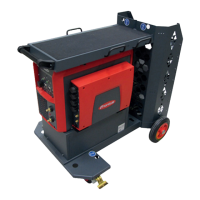
1
Connect the gas hose to the pres-
sure regulator and to the Gas IN
connection on the calibration sys-
tem
max. supply pressure: 5 bar
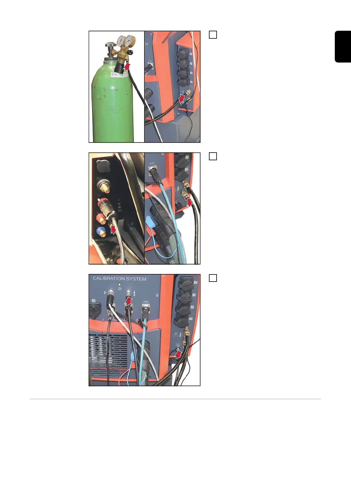
2
Connect the gas hose to the
wirefeeder or the power source
and to the Gas OUT connection on
the calibration system
3
Connect the gas and data connec-
tions to each other
Calibrating
WeldCube Con-
nector
IMPORTANT! Before starting the calibration process:
-
All devices to be calibrated must be connected to the calibration system:
power source, wirefeeder, shielding gas supply; etc.
-
The power source to be calibrated must be switched on at least 5 minutes
before the calibration process starts.
The calibration process is started from the calibration software on the com-
puter / laptop.
85
EN