(16) Gas IN connection socket (option)
(17) Gas OUT connection socket (option)
(18) Data connection socket (option of connecting to the calibration system)
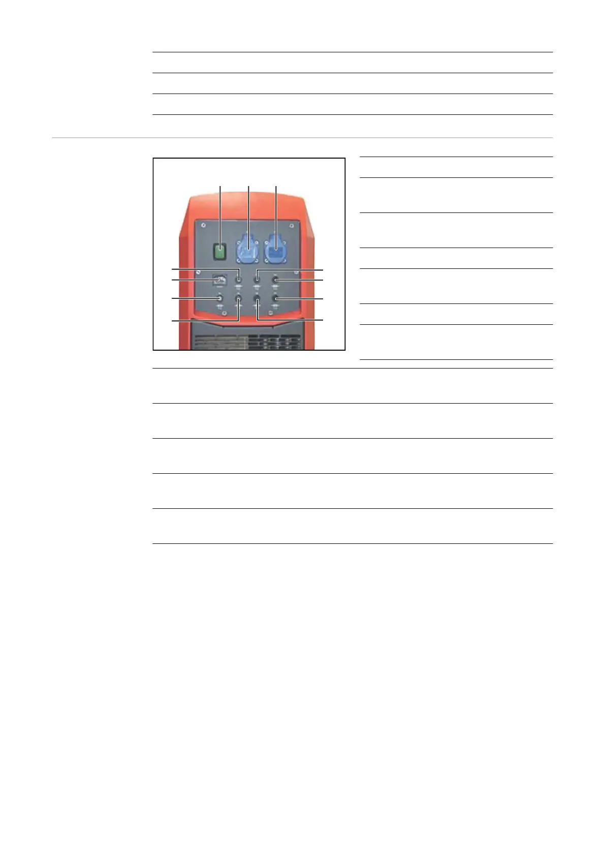
Rear of device
(without trolley)
(1)
(2)
(3)
(4)
(5) (6) (7)
(8)
(11)
(10)
(9)
Item Designation
(1) F5 fuse (2 A slow-blow)
24 V PLC fuse protection
(2) F4 fuse (2 A slow-blow)
24 V PLC fuse protection
(3) Mains cable connection
(4) Main fuse for the device F1
(4 A slow-blow)
(5) Mains switch
(6) 230 V socket
(for 230 V power supply)
(7) 230 V socket
(for 230 V power supply)
(8) F2 fuse (1 A slow-blow)
AC voltage measurement fuse protection
(9) F3 fuse (1 A slow-blow)
AC voltage measurement fuse protection
(10) F7 fuse (1 A slow-blow)
Automatic start/stop fuse protection
(11) F6 fuse (8 A slow-blow)
24 V fan fuse protection
26