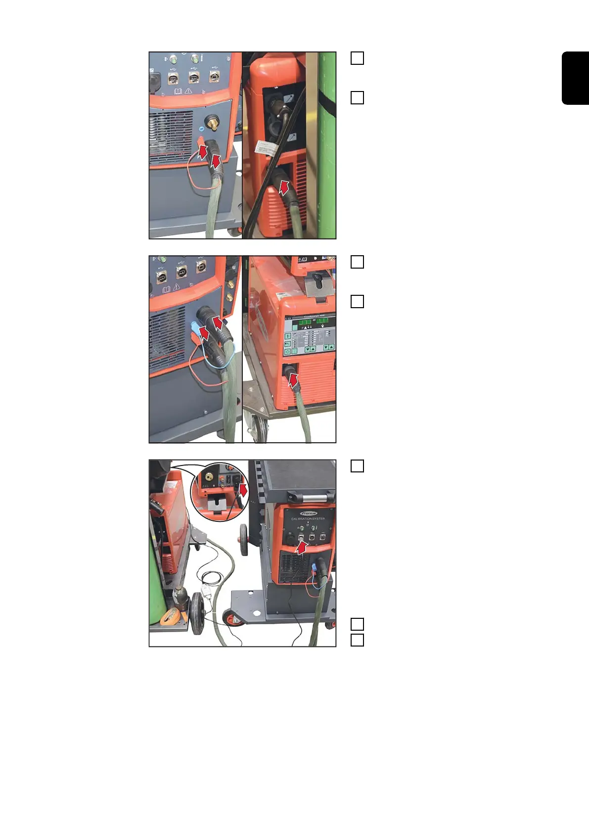
3
Connect the (+) power cable to the
calibration system and the power
source
4
Connect the sense lead (red) to the
calibration system
5
Connect the (-) power cable to the
calibration system and the power
source
6
Connect the sense lead (blue) to
the calibration system
7
Connect the LocalNet/USB con-
verter to the calibration system
and to a free LocalNet port on the
welding system
If there is no LocalNet port avail-
able, use the LocalNet passive dis-
tributor (4,100,261)
e.g. for TSt 5000
8
Switch on the power source
9
Start calibration
For TransSteel TSt 2200c only:
A cable harness (item number 43,0004,4850) is also required when calibrating a
TSt 2200c power source.
The calibration process is performed with an open power source housing.
43
EN