122
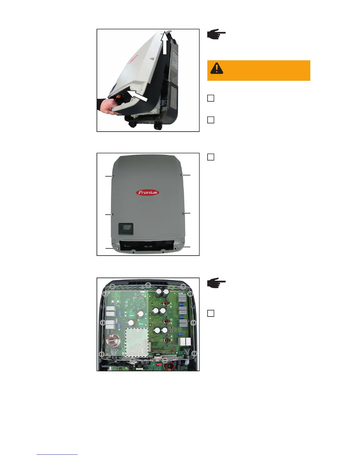
Lift the inverter from the Datcom area,
disconnecting the connection to the
wall bracket
Detach the inverter by lifting it upwards
Undo the six 5x16 TX25 screws and
seal rings (4) and remove the power
stage set cover by lifting it clear
Closing the device:
Symo 10-20 (US), Eco (15)
Make sure that the eleven EMC
springs are seated correctly - slight
notches hold the EMC springs in place
(The Overvoltage PC board is necessary
on position (5))
(1)
1
2
NOTE! To avoid damaging the
base shell, do not angle the invert-
er by more than 11°.
WARNING! Wait for the capaci-
tors to discharge before continu-
ing.
5
6
(4)
(4)
(4)
(4)
(4)
(4)
7
(5)
NOTE! To ensure a sufficient
EMC connection is established, all
EMC springs must be present
1