EasyManuals Logo

Fronius Symo Service Manual

Fronius Symo
Go to English
180 pages
To Next Page IconTo Next Page
To Previous Page IconTo Previous Page
Page #123 background imageLoading...
Page #123 background image
123
EN
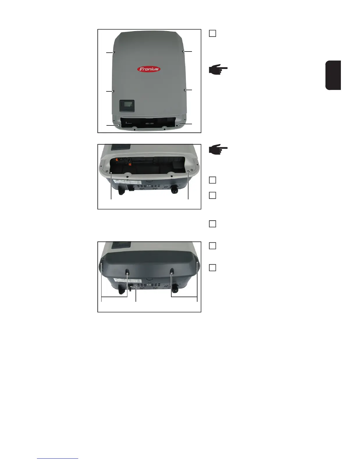
Fit the power stage set cover with six
5x18 TX25 screws and seal rings (4)
[3 Nm]
Attach the inverter at the top and allow
it to engage in the wall bracket
Fit the two 5x25 TX25 screws (3) to
hold the inverter securely in the wall
bracket
[2.5 Nm]
If applicable, connect all plug connec-
tions
Fit the Datcom cover with four 5x25
TX25 screws (2)
[2.5 Nm]
Set the DC disconnector (1) to the I po-
sition
(4)
(4)
(4)
(4)
(4)
(4)
NOTE! If the screws no longer fit
tightly, they must be replaced with
new 5x25 TX25 screws
[42,0401,4231]
2
(3) (3)
NOTE! To avoid damaging the
base shell, do not angle the invert-
er by more than 11°.
3
4
5
(1)(2) (2)
6
7

Table of Contents

Other manuals for Fronius Symo

Questions and Answers:

Question and Answer IconNeed help?

Do you have a question about the Fronius Symo and is the answer not in the manual?

Fronius Symo Specifications

General IconGeneral
THD< 3 %
Number of MPP Trackers2
Protection ClassIP65
Frequency Range50 / 60 Hz
Operating Temperature Range-25°C to +60°C
Power Range3.0 kW - 20.0 kW
AC Output Voltage230 V
CommunicationEthernet
Warranty5 years
ModelSymo

Related product manuals