TROUBLE-SHOOTING
7-10 User's Manual
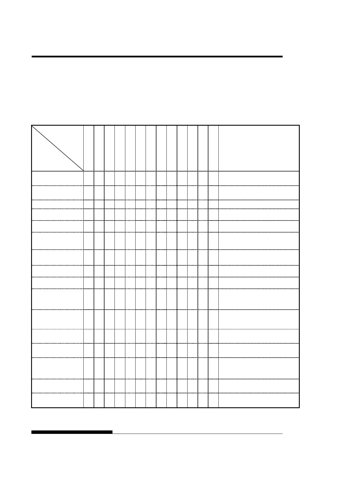
Alarm display function(LED)
This printer has a function for distinguishing between alarms by using
the blinking of individual lamps on the control panel.
From the combination of blinking lamps in an alarm state, the meaning
of the alarm can be determined as shown in the following table.
Lamp
Condition of occurrence
RES alarm
LRES could not be detected during the
space initial operation.
The shield board could not be detected
normally by the LRES sensor.
The cooling fan could not rotate.
Fire check alarm
SP motor
Abnormally high current of motor driver
was detected.
Fire check alarm
Ribbon motor
Abnormally high current of motor driver
was detected.
Detect the jam of the ribbon.
Detect the ribbons other than the genuine
HCPP (cut sheet or
continuous
forms paper
Switching between cut sheet paper and
continuous forms paper was not possible.
Fire check alarm
LF motor
Abnormally high current of motor driver
was detected.
Fire check alarm
CSF motor
Abnormally high current of motor driver
was detected.
An overload occurred during printing, and
second pass printing was performed.
However, the power source voltage was
The power source voltage dropped below
the specified level when no printing was
progress.
Fire check alarm
Print Head
Abnormally long driving of print head
driver was detected.
voltage alarm
Over voltage of power source was
detected.
During the APTC operation, paper was
detected immediately after the start of
approach motion, or no paper was
me position
During the APTC operation, no reference
position was detected.
A sum-check error or read/write error
occurred, or no CG-ROM is mounted.
: Blinking
Blank: Off