Questions? Please Contact Your Local Manufacturer’s Representative
SECTION 2 VTG-IOM-2016-1214 INSTALLATION
2-15
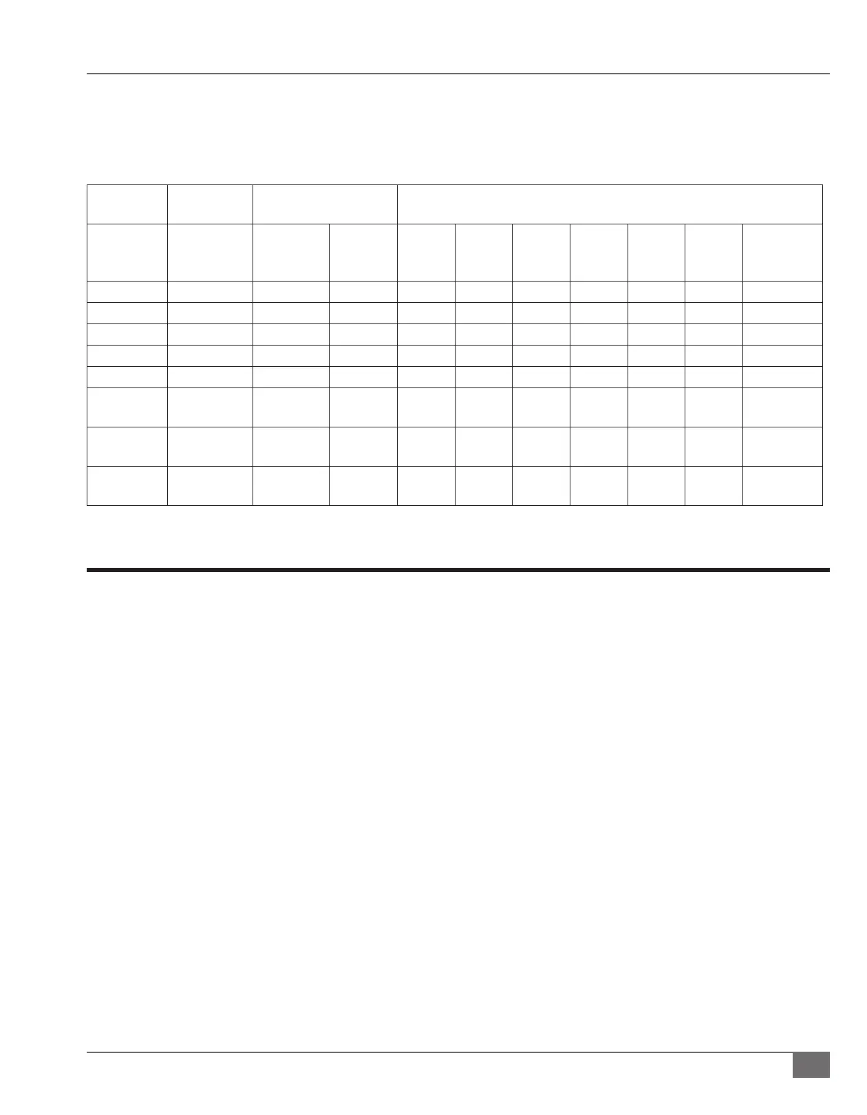
TABLE 3 NOMINAL PIPE SIZE
Nominal
Pipe Size
ID Equivalent Pipe
Length
Max Capacity in ft3 of natural gas per hour. Pressure drop of 0.5”wc/
Equivalent length of pipe (feet); incoming pressure of 14”W.C.
Inch (mm) Inch (mm) 90 Elb
Feet
(meter)
Tee
Feet
(meter)
20 40 60 80 100 150 200
1-1/4 (31.75) 1.380 (35.05) 3.45 (1.05) 6.9 (2.10) 950 ----- ----- ----- ----- ----- -----
1-1/2 (38.1) 1.610 (40.89) 4.02 (1.22) 8.04 (2.45) 1460 990 810 ----- ----- ----- -----
2 (50.8) 2.067 (52.50) 5.17 (1.57) 10.3 (3.13) 2750 1900 1520 1300 1150 950 800
2-1/2 (63.5) 2.469 (62.71) 6.16 (1.87) 12.3 (3.74) 4350 3000 2400 2050 1850 1500 1280
3 (76.2) 3.068 (77.92) 7.67 (2.33) 15.3 (4.66) 7700 5300 4300 3700 3250 2650 2280
4 (101.6) 4.026
(102.26)
10.10 (3.07) 20.2 (6.15) 15800 10900 8800 7500 6700 5500 4600
6 (152.4) 6.07 (154.17) 10.10 (3.07) 23.60
(7.19)
----- ----- ----- ----- 20200 16503 12766
8 (203.2) 7.98 (202.69) 13.30 (4.05) 29.10
(8.86)
----- ----- ----- ----- 41200 33660 29128
Install Condensate Drain
A condensate drain trap is intended for use with the Fulton Vantage boiler.
Single Boiler Drain Trap
The single boiler condensate drain trap is Fulton Part Number 4-57-005500. The drain trap must be congured one per boiler,
with a maximum capacity of 4.0 MM BTU/hr. See Figure 5 and 9.
Adhere to the following for installation:
1. The 1 inch (25.4 mm) boiler condensate drain outlet will be reduced and connected to the 3/4 inch (19.05 mm) inlet on
the top of the drain trap.
2. A condensate collecting tank and condensate pump will be required if a oor drain is not available to collect condensate
(collecting tank and pump are not supplied with the boiler).
3. All piping (Figure 5) must be galvanized or stainless steel, and be free of leaks. Copper, carbon steel/iron pipe, PVC or
CPVC are not acceptable.
4. The 3/4 inch (19.05 mm) drain outlet must remain below the 1 inch (25.4 mm) boiler condensate drain.
5. Connect the 3/4 inch (19.05 mm) drain outlet to an appropriate waste line following applicable codes. The 3/4 inch (19.05
mm) drain connection on the drain tank must be the highest point prior to going to the drain. Failure to keep drain piping
lower than this point will result in overow of the drain tank. Slope the drain pipe away at a minimum pitch of 1 inch (25.4
mm) for every 12 feet (3.65 m).
NOTE: Ensure condensate drain piping will not be exposed to freezing temperatures.



 To Next Page