Questions? Please Contact Your Local Manufacturer’s Representative
SECTION 2 VTG-IOM-2016-1214 INSTALLATION
2-39
4. Pass the vent pipe through the thimble from the
outside and join to the rest of the vent system. Seal the
pipe to the thimble ange with adhesive material.
5. Install two pipe retaining clamps around the intake as
well as vent pipes on both ends of the wall thimble (on
the inside and outside of the wall) through which intake
and vent pipes are passed. They will prevent the intake
and vent pipes from being pushed or pulled.
Roof Vent Termination
Adhere to the following for installation:
1. The minimum vent height should extend at least 3 feet
(0.9 m) above the roof, or at least 2 feet (0.6 m) above
the highest part of any structure within 10 feet of the
vent.
2. When installing inlet and exhaust terminations above
the roof, the exhaust outlet must be installed 4 feet
(1.22 m) minimum above and 4 feet (1.22 m) minimum
downwind from air supply inlet to prevent exhaust
recirculation.
Side Wall Vent Termination
Adhere to the following for installation:
NOTE: The vent termination is joined to the vent pipe outside
the wall. Use the same joining procedures for vent pipe and
ttings.
1. When penetrating a non-combustible wall, the hole
through the wall must be large enough to maintain
the pitch of the vent and provide sealing. Use adhesive
material to seal around the vent on both sides of the
wall. When penetrating a combustible wall, a wall
thimble must be used. Minimum wall thickness through
which vent system may be installed is 3.25 inches (8.26
cm). Maximum wall thickness through which vent
system may be installed is 20 inches (50.8 cm).
2. The termination of the vent system must be at least 12
inches (30.48 cm) above the nished grade, or at least
12 inches (30.48 cm) above normal snow accumulation
level (for applicable geographical areas).
3. The termination of the vent system shall not be located
in trac areas such as walk ways, adjacent buildings,
operable windows and building openings unless the
venting system is at least 7 ft (2.1 m) above nished
grade, (National Fuel Gas Code, ANSI Z223.1).
4. The vent terminations must be at least 4 ft (1.22 m)
horizontally from electric meters, gas meters, regulators,
and relief equipment.
5. When installing inlet and exhaust terminations on the
same wall, the exhaust outlet must be installed 4 feet
(1.22 m) minimum above and 10 feet (3.05 m) minimum
downwind from air supply inlet to prevent exhaust
recirculation.
6. Under certain wind conditions, some building materials
may be aected by ue products expelled in close
proximity to unprotected surfaces. Sealing or shielding
of the exposed surfaces with a corrosion resistant
material (such as an aluminum sheet) may be required
to prevent staining or deterioration. Flue should be
directed away from surfaces, if possible.
Removing an Existing Boiler
When an existing boiler is removed from a common venting
system, the common venting system is likely to be too large
for proper venting of the appliances remaining connected to
it.
At the time of removal of an existing boiler, while the other
appliances remaining connected to the common venting
system are not in operation, the following steps should be
followed with each appliance remaining connected to the
common venting system placed in operation:
1. Seal any unused openings in the common venting
system.
2. Visually inspect the venting system for proper size
and horizontal pitch and determine that there is no
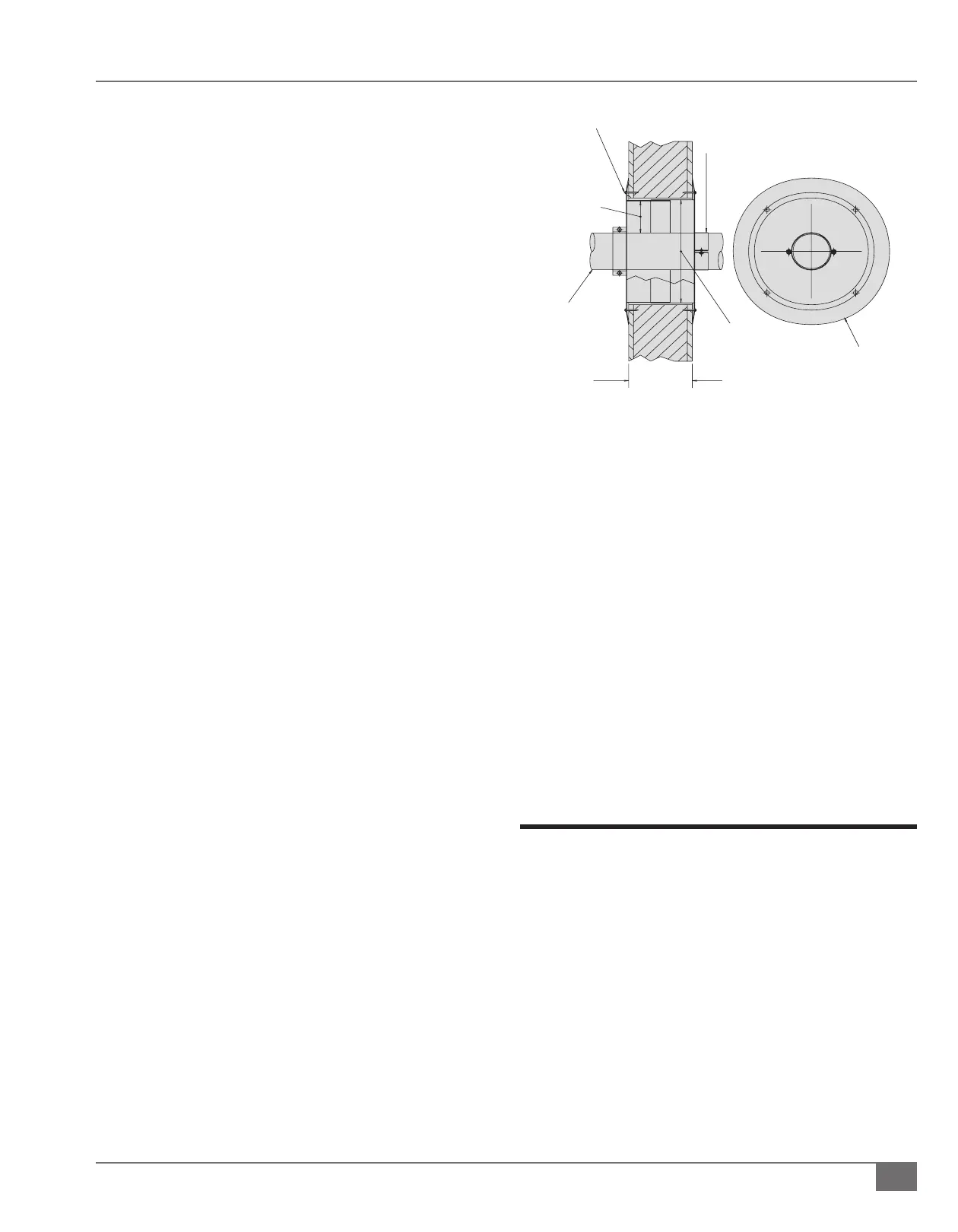
FIGURE 22 WALL THIMBLE INSTALLATION
VARIABLE
(MIN. 3 ¼ IN) – (MAX. 20 INCHES)
(MIN. 8,255 CM – MAX. 50,8 CM)
SCREW OR BOLT EACH THIMBLE COLLAR TO WALL
(TYPICAL 4 PLACES)
ORIENT CLAMPS AND COLLAR AS REQUIRED
PIPE RETAINING
CLAMP, TYPICAL
EACH SIDE
3½ INCH OR
4.35 CM AIR GAP
ALL AROUND
THRU PIPE
DIAMETER “C”
STAINLESS
DIAMETER “B”
ADJUSTABLE
WALL THIMBLE
WIDTH TO VARY WITH
WALL THICKNESS
DIAMETER “A” COLLAR
END VIEW