© The Fulton Companies 2016
INSTALLATION VTG-IOM-2016-1214 SECTION 2
2-24
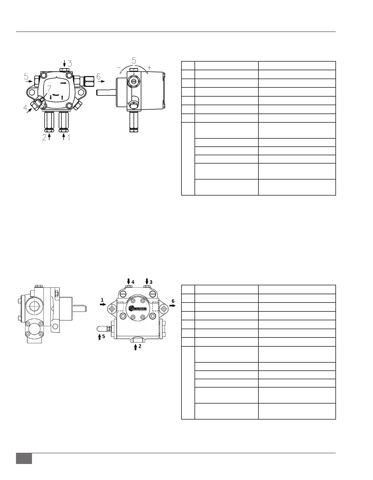
FIGURE 13 OIL PUMP DETAILS VTG5000DF/VTG6000DF
FIGURE 12 OIL PUMP DETAILS VTG2000DF TO VTG4000DF
Figure 12 Notes
Characteristic Connection/Detail
1
Suction 3/8” NPT (Piped in the Field)
2
Return 3/8” NPT (Piped in the Field)
3
Pressure Gauge Attachment G 1/8” (Completed at Factory)
4
Vacuum Gauge Attachment G 1/8” (Completed at Factory)
5
Pressure Regulator
6
Outlet to Burner ¼” NPT (Completed at Factory)
Minimum Delivery Rate at 174
PSI Pressure
54 GPH (204.41 LPH)
Delivery Pressure Range 145 – 290 PSI (997.7 - 1999.5 k Pa)
Maximum Suction 13 “ Hg
Oil Viscosity Range 2.8 – 75 cSt
Maximum Fuel Oil
Temperature
140 F (60 C)
Pressure Calibration at the
Factory
198-200 PSI (1365 - 1379 kPa)
Figure 13 Notes
Characteristic Connection/Detail
1
Suction 1/2” NPT (Piped in the Field)
2
Return 1/2” NPT (Piped in the Field)
3
Pressure Gauge Attachment G 1/4” (Completed at Factory)
4
Vacuum Gauge Attachment G 1/4” (Completed at Factory)
5
Pressure Regulator
6
Outlet to Burner 1/2” NPT (Completed at Factory)
Minimum Delivery Rate at 174
PSI Pressure
132 GPH (500 LPH)
Delivery Pressure Range 102-435 PSI (703 - 3000 k Pa)
Maximum Suction 13 “ Hg
Oil Viscosity Range 3 – 75 cSt
Maximum Fuel Oil
Temperature
302 F (150 C)
Pressure Calibration at the
Factory
365-385 PSI (2516.6 - 2654.5 kPa)