© The Fulton Companies 2016
INSTALLATION VTG-IOM-2016-1214 SECTION 2
2-36
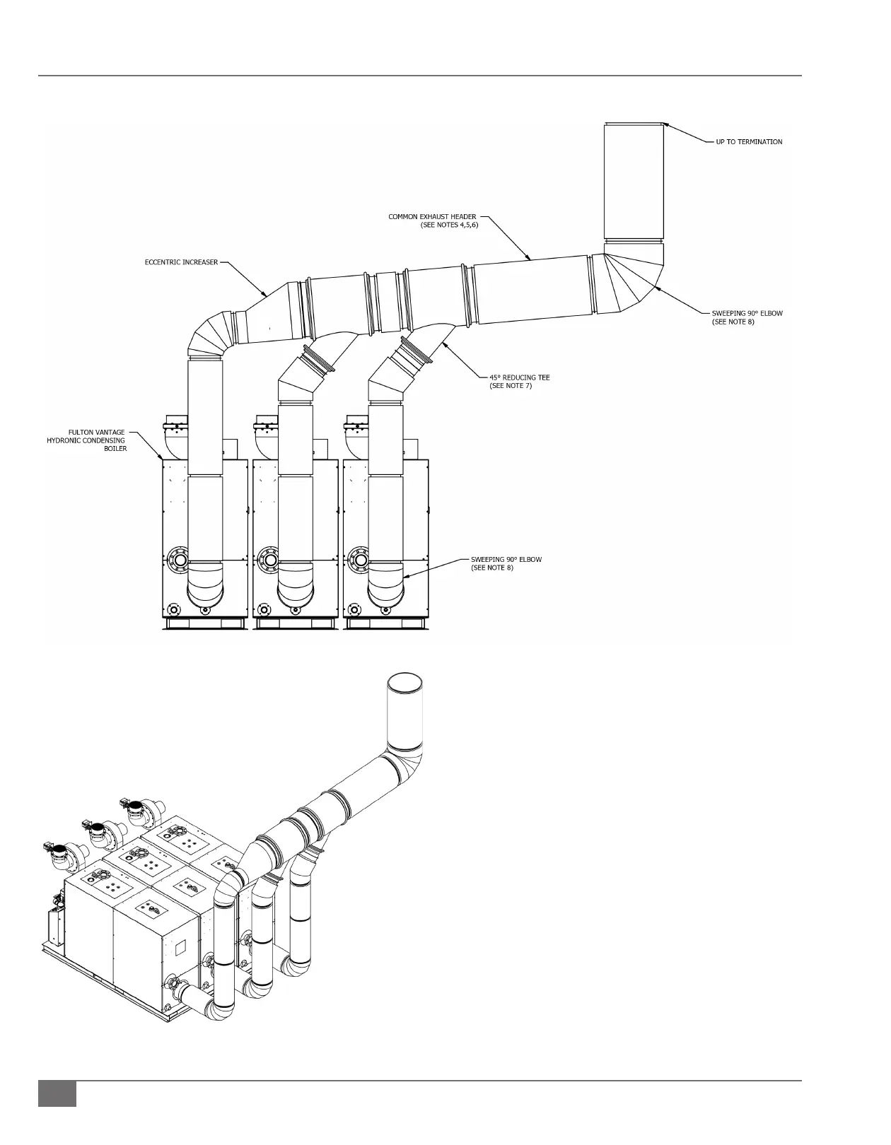
FIGURE 19 TYPICAL COMMON EXHAUST LAYOUT
REAR VIEW
ISOMETRIC VIEW
Figure 19 Notes:
1. This is a typical arrangement for reference purposes only.
Actual installations may require alternate or additional
components which are not shown for clarity.
2. This drawing is not for construction purposes.
3. Adhere to clearance and installation requirements.
4. The common exhaust header should be maintained
at a slight negative pressure within the requirements
of the boiler. A positive pressure common header will
require accessories to guarantee ue gases cannot travel
backward through an idle boiler.
5. A constant diameter common header is recommended.
Do not use the static regain method.
6. A minimum 1/4” rise per foot run is required.
7. A 45° reducing tee or elbow in the direction of ow is
recommended. Straight or 90° tees must not be used.
8. Do not use boot tees or bull head tees.
9. Vantage boilers cannot be common vented with other
equipment.