2.1 Configuration
2-3
TERM/CPU
(16P0209)
Communicating with followings;
LCD, Printer, PC, Distress Alert Received
unit, ALERT unit, NAV data, Ethernet,
FDD, keyboard and RF-CON/CPU board.
I/F rating
- Printer: Centronics
- PC: RS-232C
- Distress Alert Received/
ALERT unit : RS-485
- NAV data inputting:
GGA, GLL, WPL, VTG,
RMA, RMB, RMC, MTW,
DBT, VDR, BWC, BWR
and ZDA
PWR
(16P0211)
Switching power supply
Input voltage: 10.8 V to 31.2 V
Maximum input current: 13 A (When
inputting 10.8 V)
Output voltage: 29, 7, 6.5, 3.3, 5 V and
LCD power supply
Detecting status monitor signal:
- CHECK V: Antenna Power supply
- ANT C: Send Level
Changing ANT TX/RX power supply by
HPA ON signal
SW
(16P0212)
Consisting of the distress alert button, the
buzzer and the power switch.
PWR C
(16P0214)
Consisting of the bypass capacitor for
EMC and the power reverse
connection protector diode.
GPS
Receiver
(GN-79)
12 CH parallel GPS receiver. Outputs
GLL, GGA, VTG, RMC, GSV and ZDA by
IEC-61162 data.
Option
MCN
(16P0226)
Relay board for wiring between Term CPU
board and LCD.
FDD FDD for 2HD and 2DD FD
Terminal
unit
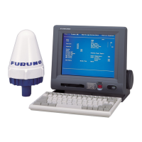
(IC-215)
LCD
640x480 dots and 262,144 color display.
(In specification, IC-215 display uses 16
colors.)
Junction
box
(IC-315)
Junction box for [JUNCTION] port of
terminal unit. Terminal board only.
Option
Distress
Alert
Received
unit and
ALERT
unit
(IC-305/
306)
DIST
(16P0213A)
RCV
(16P0213B)
Consisting of I/F and the driver which
communicates with Term CPU board by
RS-485 signal conductor.
Communication contents: The control of
the buzzer and the button and the
recognition of the unit number.
IC-305 and IC-306 have the
same board.
Maximum of 3 IC-306 unit
and IC-305 unit are
connected in parallel.
The setting of the unit
recognition number is
necessary.