2.2 Antenna unit, IC-115
2-4
2.2 Antenna unit, IC-115
The antenna unit consists of ANT RF board (16P0207), ANT B(16P0206) and the daisy
loop type antenna element.
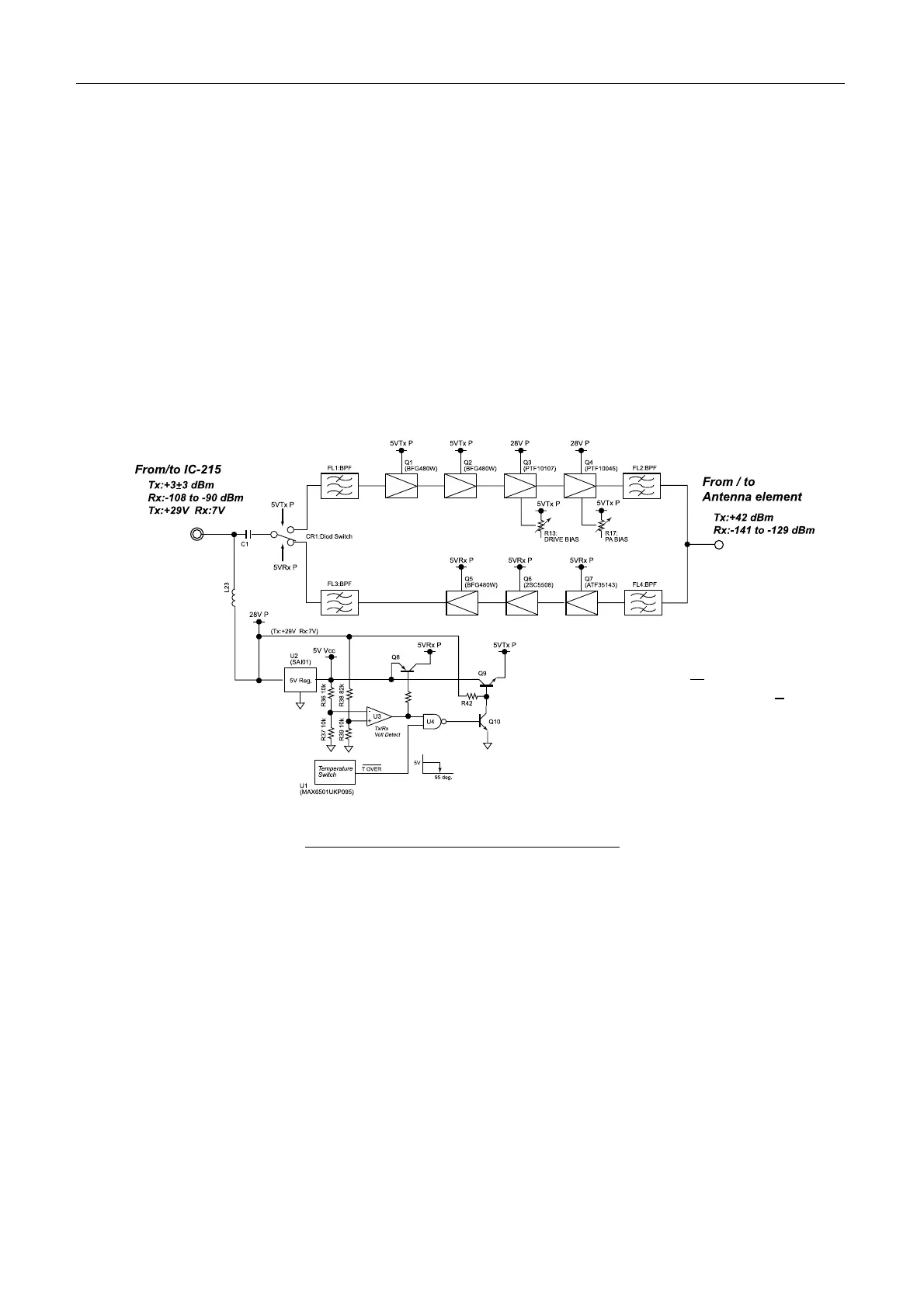
2.2.1 ANT RF board (16P0207)
ANT RF board consists of the transmitting RF amplifier circuit, the receiving RF
amplifier circuit, the voltage changing circuit of TX/RX circuit and the heat protecting
circuit. The band pass filter is installed at the input/output unit of RF circuit to divide
RF signal. Fig.2.2.1 shows the block diagram of the ANT RF board.
Fig.2.2.1 Block diagram of ANT RF board
To control the voltage changing of TX/RX circuit, the voltage, 29 V (TX)/7 V (RX)
supplied from the terminal unit is detected by the comparator, U3. The output controls
Q8 and Q9 to generate the voltage of 5 V RX P and 5 V TX P.
The heat protector is installed to stop the transmission automatically when the
temperature of the board is more than +95 °C. To detect the heat of the board, the heat
detecting switch, U1 is installed on the center of the ANT RF board. When detecting
+95 °C, 5VTx P is set to OFF via NAND, U4 to stop the transmission.
• Receiving gain: 36d B+ 3dB NF=2.0 dB max.
• Transmitting gain: Changing +3 +
3 dBm, to +
42 dBm
• Continuous-time of transmitting: 8 minutes