2.3 Terminal unit, IC-215
2-16
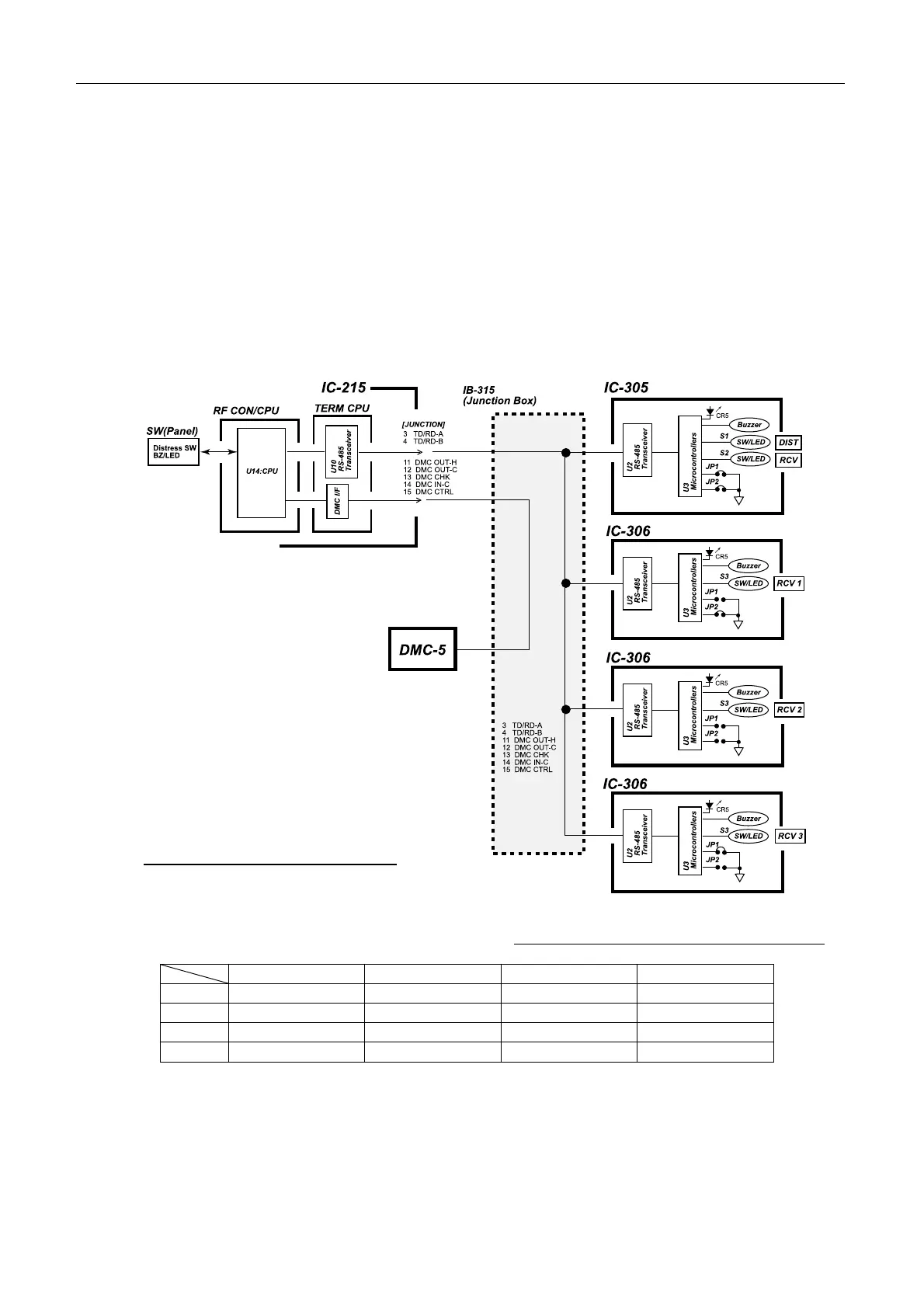
6) Connecting IC-305 and IC-306
The Distress Alert Received unit, IC-305 and Alarm unit, IC-306 (a maximum of 3) are
connected to RF CON/CPU board via RS-485 rating interface.
The function of the distress alert and the incoming indicator of the distress message and the
emergency messages are provided to IC-305.
IC-305 and IC-306 are connected in parallel. Each unit is recognized by the jumper setting.
RF CON/CPU board is communicated with IC-305 and IC-306 at 1200 bps. No regular
communication with DMC-5.
Fig.2.3.13 shows the IC-305 and IC-306 connection.
Table 2.3.3 Jumper setting of IC-305/306
IC-305 (DIST) IC-306 (RCV1) IC-306 (RCV2) IC-306 (RCV3)
JP 1 Jumper Open Jumper Open
JP 2 Jumper Jumper Open Open
S1, 2 Yes No No No
S3 No Yes Yes Yes
Fig.2.3.13 IC-305/306 connection