GAT Access 6100 Terminal Series
Installation
20
HB_GAT-ACCESS6100--EN_14
www.gantner.com
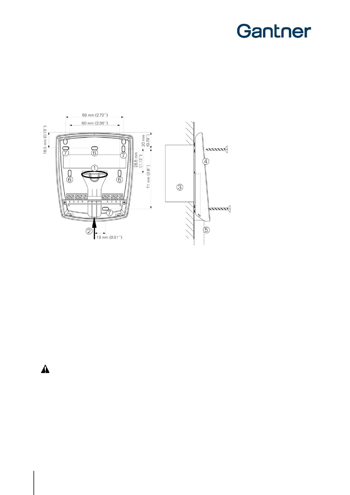
3.3 GAT Access 6100 Installation
First, the rear part of the GAT Access 6100 is attached to a flat surface, e.g., a masonry or plaster wall, using 3 screws
(6) according to the following measurements.
1. Access for flush-mounted cabling
2. Access for surface-mounted cabling
3. Back box
4. Device rear part
5. Conduit for surface-mounted cabling
6. Mounting holes
Figure 3.1 - GAT Access 6100 installation measurements
Cable Inlets
The housing of the GAT Access 6100 has cable inlets for either flush (1) or surface (2) mounted cabling. For surface-
mounted cabling, ensure that the cabling can still be inserted once the device rear part has been installed. Otherwise,
run the cabling through the cable lead-ins prior to mounting.
CAUTION! The connection of the cabling must always be performed in a powerless state. See chapter "4
ELECTRICAL CONNECTIONS" for more information.
Installing the Device Front Part
Once the connection cables are terminated, the device rear part and front part are connected together via a connection
cable (already connected to the part) and the two parts are fixed together.
 Loading...