GAT Access 6100 Terminal Series
Installation
24
HB_GAT-ACCESS6100--EN_14
www.gantner.com
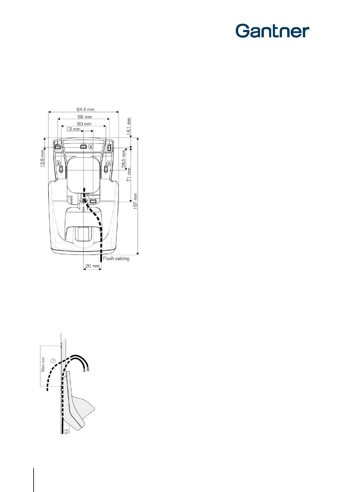
3.5 GAT Access 6100 F BIO Installation
First, the rear part of the GAT FR 055 reader is attached to a flat surface, e.g., a masonry or plaster wall, using 3
screws (a) according to the following measurements.
Figure 3.7 - Dimensions of GAT FR 055 rear part and mounting holes (a)
Connection Cables
The connection cables (power supply, network etc.) are run through the cable lead-ins of the GAT FR 055. For flush-
mounted cabling (1), the connection cables are fed from behind via the back box. For surface-mounted cabling (2),
the connection cables must lie in the cable duct on the rear part of the GAT FR 055.
Figure 3.8 - Dimensions of GAT FR 055 rear part and mounting holes (a)
 Loading...