Chapter 1: Installation and wiring
Vigilant VS1 and VS2 Technical Reference Manual 13
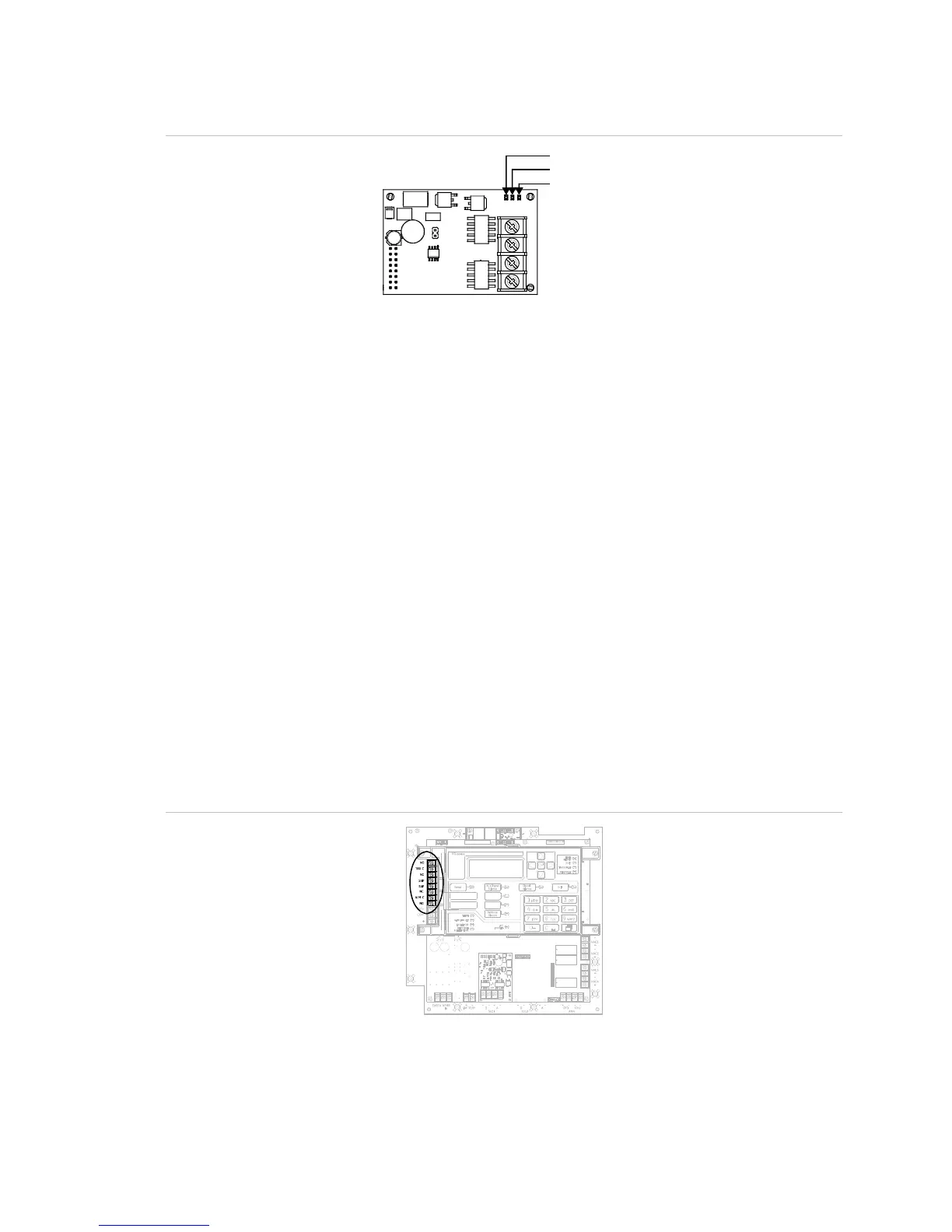
Figure 18: Loop card LEDs
Primary
Secondary
omm
“Comm” refers to overall communication
Alarm, trouble, and supervisory relay wiring (TB3)
The control panel provides alarm, trouble, and supervisory relays.
• The trouble relay changes over on any trouble event (common trouble)
• The supervisory relay changes over on any supervisory event (common
supervisory)
• The alarm relay changes over on any alarm event (common alarm)
Note: Relay circuits can only be connected to power-limited sources. Relays are not
supervised.
Relay specifications
• Alarm and trouble: Form C, 24 VDC at 1 A resistive
• Supervisory: Form A, 24 VDC at 1 A resistive
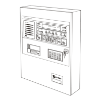
Figure 19: Terminal wiring location