Chapter 1: Installation and wiring
16 Vigilant VS1 and VS2 Technical Reference Manual
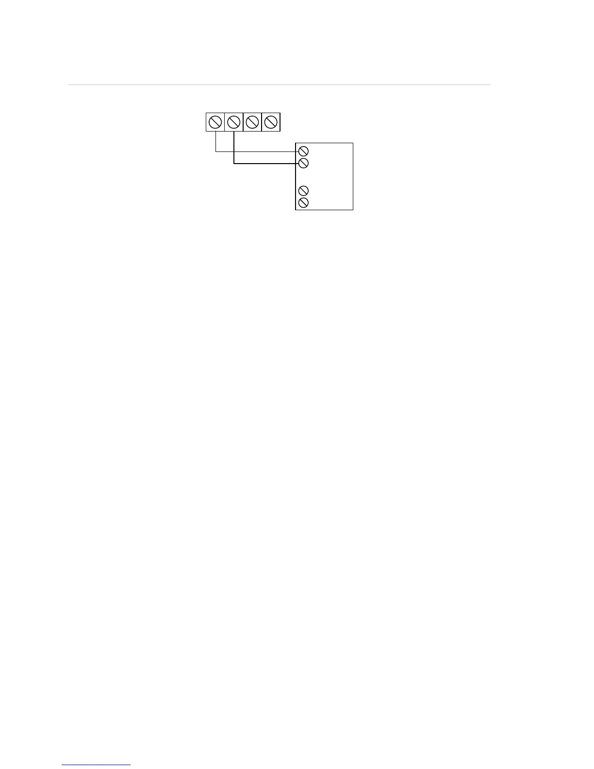
Figure 23: Annunciator channel wiring (Class B)
+
–
TB4
+
–
hannel 1
hannel 2
CH1 (+) IN
CH1 ( ) IN
–
CH2 (+) IN
CH2 ( ) IN
–
Annunciator
Auxiliary/smoke power output wiring (TB3)
The control panel provides resettable and continuous AUX power output circuits. Use
the resettable AUX power output for devices such as four wire detectors or beam
detectors. Use the continuous AUX power output for devices such as remote
annunciators or door holders.
Note: If you do not need resettable AUX power, you can configure the resettable AUX
power output to supply continuous power.
Note: For a complete list of devices that can be connected to this circuit, refer to the
VS1 and VS2 Series Compatibility List (P/N 3101065).
Circuit specifications
• Circuit voltage range: 21.9 to 28.3 V
• AUX 1 + AUX 2 can supply 1.5 A total. If more than 1.5 A is required, you must use
a power-limited and regulated 24 VDC auxiliary/booster power supply that is
UL/ULC listed for fire protective signaling systems.
• Continuous circuit (AUX power 1): 24 VDC nominal at 500 mA. Use this circuit to
supply 24 VDC continuous power. A SMK module is required when using the GSA-
UM module to support two-wire smoke detectors.
• Resettable circuit (AUX power 2): 24 VDC nominal at 500 mA (1 A possible if you
reduce total available NAC power by 500 mA). Use this circuit provide 24 VDC
resettable power.
• Special application circuits
• Ground fault impedance: 0 to 5 kΩ
• Supervised and power-limited