EasyManuals Logo

GE Security Vigilant VS1 User Manual

GE Security Vigilant VS1
284 pages
To Next Page IconTo Next Page
To Previous Page IconTo Previous Page
Page #40 background imageLoading...
Page #40 background image
Chapter 1: Installation and wiring
28 Vigilant VS1 and VS2 Technical Reference Manual
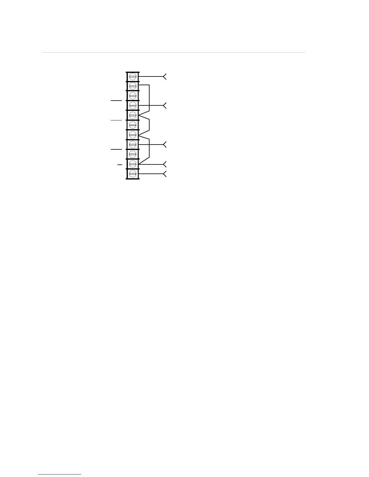
Figure 42: Alarm, supervisory, and trouble transmitted on separate circuits
From ALRM on RPM (brown wire)
From TRBL on RPM (yellow wire)
From COM on RPM (black wire)
From +24 on RPM (red wire)
From SUPV on RPM (orange wire)
C
ontrol panel
TB3
TRBL
C
NC
SUP
NC
ALM
24VOUT
+
NO
C
NO
+
Note: JP1 on the RPM must be IN.

Table of Contents

Questions and Answers:

Question and Answer IconNeed help?

Do you have a question about the GE Security Vigilant VS1 and is the answer not in the manual?

GE Security Vigilant VS1 Specifications

General IconGeneral
BrandGE Security
ModelVigilant VS1
CategoryControl Panel
LanguageEnglish

Related product manuals