5.7.2 Equations
This subtab allows the configuration of logic equation using thresholds, binary inputs,
GOOSE inputs and other equations as operands.
The list below shows the logic operator and their syntax:
▪ NOT: Not (operand)
▪ RISE: Rise (operand)
▪ FALL: Fall (operand)
▪ AND: operand AND operand
▪ OR: operand OR operand
▪ XOR: operand XOR operand
▪ LATCH (SET/RESET): Latch (set operand, reset operand)
5.7.3 Matrix
The matrix is used to assign which signals will close the binary outputs and trigger the
waveform and/or disturbance recorder.
Thresholds, binary inputs, GOOSE inputs and equations can be configured to close the
binary outputs and trigger the waveform and disturbance recorders.
To associate the variables (thresholds, binary inputs, GOOSE inputs and equations) with
the triggers of binary outputs, double click the cell that insects the variable row with the
binary output or trigger.
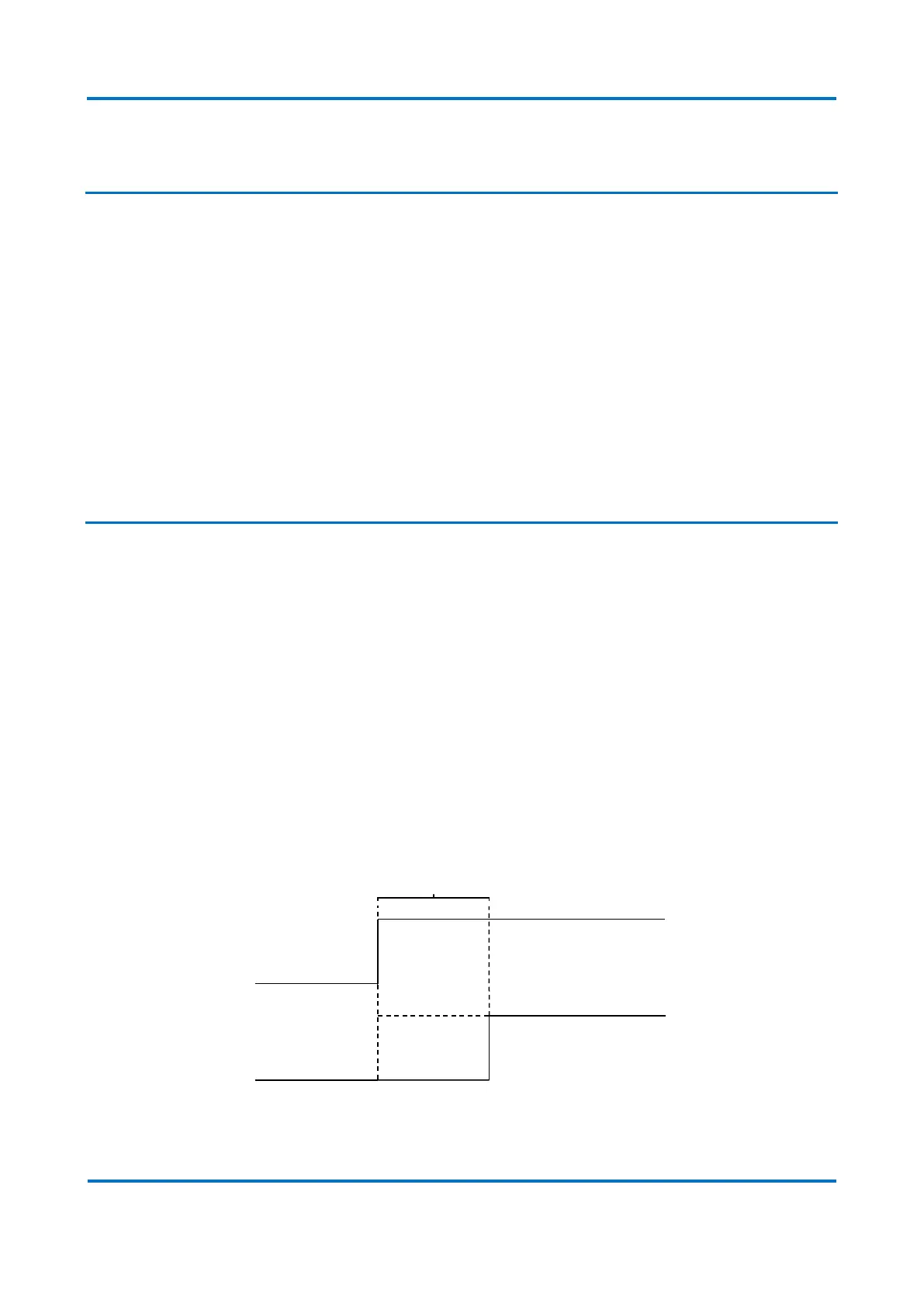
Clicking the clock sign next to the binary outputs number allows the configuration of
pickup and drop-off timer for the respect binary output operation. Within the timer
setting, the parameter Timer Value (ON) means that the signal causing the respective
output to close needs to stay ON during, at least, the time configured. The parameter
Timer Value (OFF), correspondingly, means that the signal causing the respective output
to close needs to stay OFF during, at least, the time configured. The diagram below
exemplifies the functioning of the timers.
Timer Value (ON) diagram