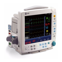
System description
2-31
Synchronization pulse
Pulse width: 10 ms positive pulse
Delay: < 35 ms (R-wave peak to leading edge of pulse)
Amplitude: CMOS compatible
3.5 V min. at 1 mA sourcing
0.5 V max. at 5 mA sinking
Output impedance: 50 ohm
Current limit: 10 mA
Hemodynamic modules E-PSM, E-PSMP
ECG
1
Filter modes:
With 50 Hz power supply frequency:
monitoring filter: 0.5 to 30 Hz
ST filter: 0.05 to 30Hz
diagnostic filter: 0.05 to 150 Hz
With 60 Hz power supply frequency:
monitoring filter: 0.5 to 40 Hz
ST filter: 0.05 to 40 Hz
diagnostic filter 0.05 to 150 Hz
QRS minimum detection level:
Minimum level 0.5 mV with duration between 40 and 120 ms.
Defibrillation protection: 5000 V, 360 J
Recovery time: <5 s
Heart rate:
Measurement range: 30 to 250 bpm
Measurement accuracy: ±5 % or ±5 bpm
Displays average of 10-second median values
2
Display update time: 1 s
Maximum response time of heart rate meter to change in heart rate:
Response time 80 to 120 bpm: 6.9 s
Response time 80 to 40bpm: 8.2 s
Maximum Tall T wave amplitude that does not disturb the heart rate calculation time: >1.4 mV
Input impendance: >2.5 Mohm
The heart rate calculation operates with irregular rhythms of IEC 60601-2-27 6.8.2 bb 4, the heart rate
after a 20 second stablization period as follows:
Figure 101 A1): 80 bpm
Figure 101 A2): 59 bpm
Figure 101 A3): 122 bpm
Figure 101 A4): 117 bpm
Pacemaker pulse detection:
detection level: 2 to 700 mV
pulse duration: 0.5 to 2 ms
Pacemaker detector may not operate correctly during the use of high-frequency (HF) surgical equipment.
The disturbances of HF surgical equipment typically cause false positive pacer detection.
Direct current for leads-off detection
through an active patient electrode: <30 nA
1 The isolation barrier capacitance in the module has been minimized to reduce the hazard of burns in the event of a
defect in the ESU return electrode connection.
2 When the heart rate (HR) changes rapidly, the averaging is restarted.

 Loading...