248
Humidifier to ensure adequate drainage to it.
The Y-transducer should always slope slightly towards the Water trap (greater
than 10
o
) to ensure adequate drainage to the Water trap.
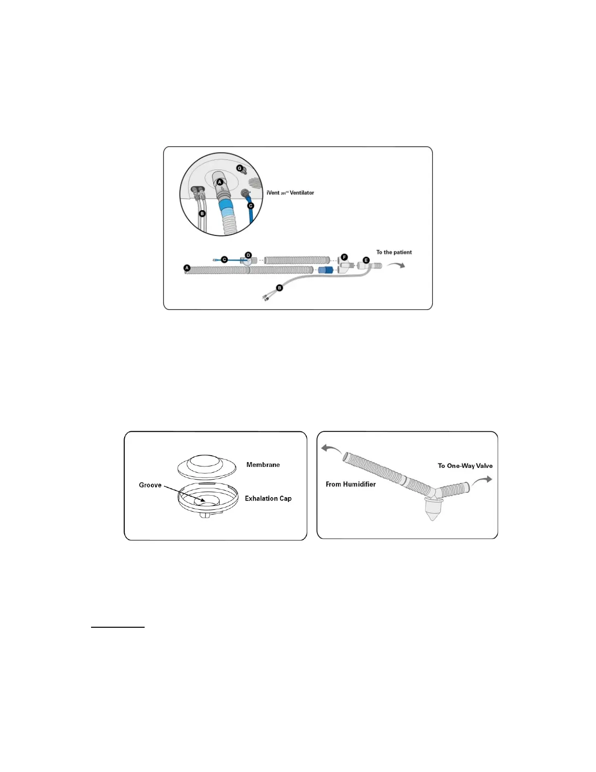
Figure 178: iVent
TM
201 Reusable Patient Breathing Circuit
Figure 179: Exhalation Valve components
Figure 180: Example of water trap tubing assembly
Cleaning and Sterilization
Disassembly
1. Detach the one-way valve from the Y-Connector and the long (inspiratory)
corrugated tube. Note: Do not remove the tube holders that support the
sensor tubes from the corrugated tube.
2. Disassemble the exhalation valve as follows: open the top cover together
with its control tube, and GENTLY remove the internal membrane. (Note: do
-
Ventilator outlet
B -
Flow sensor
C-
External exhalation valve
D- External exhalat
E- Flow sensor
F - Wye connector
G- Nebulizer outlet
 Loading...