Docking Cart Servicing
12-32 LOGIQ e – Basic Service Manual
5461614-100 English Rev. 6
Safety Test (continued)
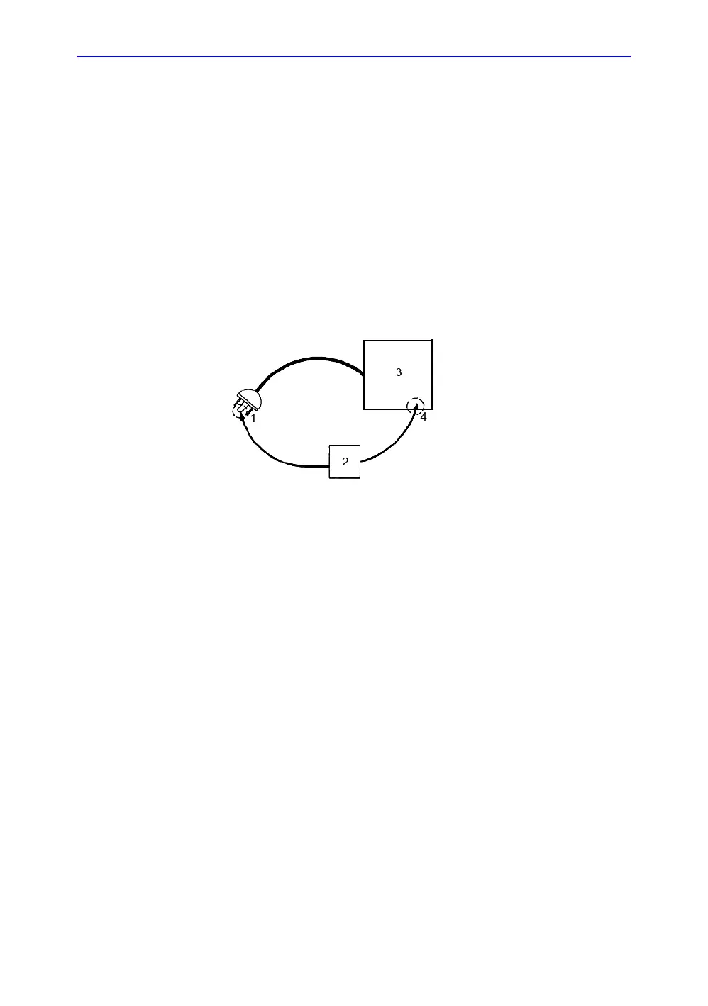
Grounding continuity
Measure the resistance from the third pin of the attachment plug
to the exposed metal parts of the case. The ground wire
resistance should be less than 0.2 ohms. Reference the
procedure in the IEC60601-1.
Figure 12-5. Ground continuity test
Meter Procedure
Follow these steps to test the ground wire resistance.
• Turn the LOGIQ e unit OFF.
• Plug the unit into the meter, and the meter into the tested
AC wall outlet.
• Plug the black chassis cable into the meter's “CHASSIS”
connector and attach the black chassis cable clamp to an
exposed metal part of the LOGIQ e unit.
• Set the meter's “FUNCTION” switch to the RESISTANCE
position.
• Set the meter's “POLARITY” switch to the OFF (center)
position.
• Measure and record the ground wire resistance.
DANGER ELECTRIC SHOCK HAZARD. THE PATIENT MUST NOT BE
CONTACTED TO THE EQUIPMENT DURING THIS TEST.
1. GROUND PIN
2. OHMMETER
3. LOGIQ e
4. ACCESSIBLE METAL PART:
• MONITOR HOUSING
• PEAR PANEL CONNECTOR
• ANY CASTER/WHEEL SUPPORT