GE HEALTHCARE
DIRECTION 5245279, REVISION 3 LOGIQ™ P6/P6 PRO SERVICE MANUAL
Section 8-2 - DISASSEMBLY/RE-ASSEMBLY 8 - 69
8-2-28 BP128 Assy
8-2-28-1 Tools
• Common philips screwdrivers
8-2-28-2 Preparations
• Shut down the system and switch off the main breaker.
8-2-28-3 Removal procedure
1.) To replace the BP128 assy, all PWAs should be removed from the nest box.
2.) Open the Side Left Cover and Side Right Cover. Refer to the 8-2-14 "Right or Left Side Cover" on
page 8-47.
3.) Open the EMI Cover L and EMI Cover R. Refer to the 8-2-24 "EMI Cover L and R" on page 8-62.
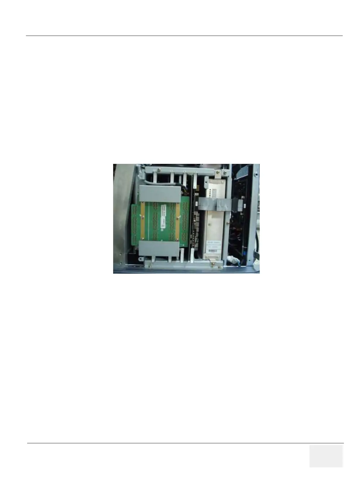
4.) Remove all PWAs from the nest box. Refer to the Figure 8-109.
5.) Open the front cover. Refer to the 8-2-15 "Front Cover" on page 8-49.
6.) Remove the P3RLY/PI128II Board. Refer to the 8-2-27 "P3RLY/PI128II Assy" on page 8-67.
7.) Remove the HDD. Refer to the 8-2-43 "SATA HDD Assy" on page 8-92.
8.) Unplug all the cable connectors all in BP128 Assy.
9.) Remove a bracket (1) by looseing 2 screws.Refet to Figure 8-110 "BP128 Assy" on page 8-70.
Figure 8-109 PWAs in the nest box

 Loading...


