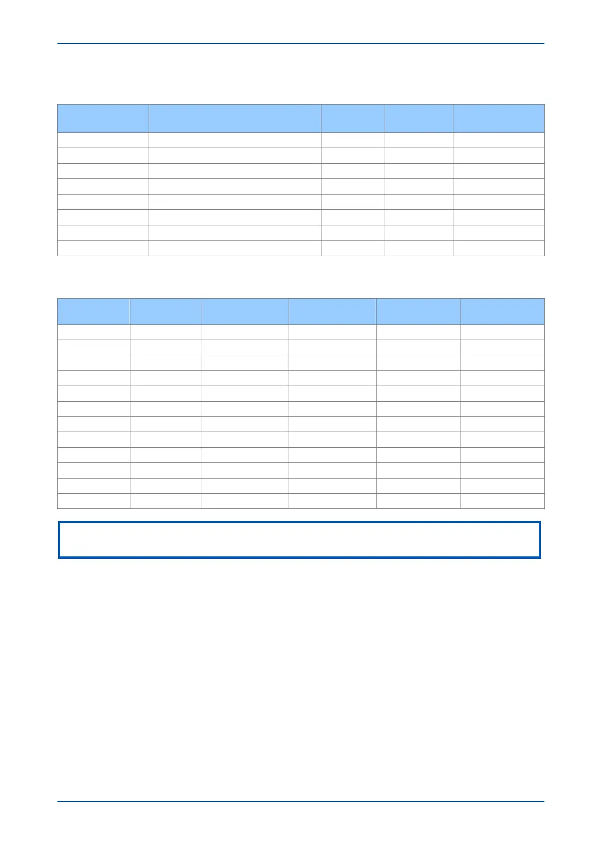
The comparators used for the Phase-Fault Quadrilateral zones are summarised in the following table:
Zone Line S1 S2
Condition
(∠S1 - ∠S2)
Forward/Offset Impedance Reach Line V – I.Z
I.Ð σº
<0º
Forward/Offset Reverse Impedance Reach Line V – I.Z’
I.Ð 3º
>0º
Forward/Offset Resistive Reach Line V – I.R I.Z >0º
Forward/Offset Reverse Resistive Reach Line V – I.R’ I.Z <0º
Reverse Impedance Reach Line V + I.Z
-I.Ð σº
<0º
Reverse Reverse Impedance Reach Line V + I.Z’
-I.Ð 3º
>0º
Reverse Resistive Reach Line V + I.R -I.Z >0º
Reverse Reverse Resistive Reach Line V + I.R’ -I.Z <0º
The positive sequence reach settings used for the Phase-Fault Quadrilateral characteristics are summarised in the
following table:
Zone Type Impedance Reach Z
Reverse Impedance
Reach Z’
Resistive Reach R
Reverse Resistive
Reach R’
1 Ph-Ph Forward Z1 Ph. Reach 0.25 Z ½*R1 Ph. Resistive 0.25 R
2 Ph-Ph Forward Z2 Ph. Reach 0.25 Z ½*R2 Ph. Resistive 0.25 R
3 Ph-Ph Forward Z3 Ph. Reach 0.25 Z ½*R3 Ph. Resistive 0.25 R
3 Ph-Ph Reverse Z3 Ph. Reach 0.25 Z ½*R3 Ph. Resistive 0.25 R
3 Ph-Ph Offset Z3 Ph. Reach Z3’ Ph Rev Reach ½*R3 Ph. Resistive ½*R3’ Ph Res. Rev.
4 Ph-Ph Reverse Z4 Ph. Reach Z ½*R4 Ph. Resistive 0.25 R
P Ph-Ph Forward ZP Ph. Reach Z ½*RP Ph Resistive 0.25 R
P Ph-Ph Reverse ZP Ph. Reach Z ½*RP Ph Resistive 0.25 R
P Ph-Ph Offset ZQ Ph. Reach ZP’ Ph Rev Reach ½*RP Ph Resistive ½*RP’ Ph. Res. Rev.
Q Ph-Ph Forward ZQ Ph. Reach Z ½*RQ Ph Resistive 0.25 R
Q Ph-Ph Reverse ZQ Ph. Reach Z ½*RQ Ph Resistive 0.25 R
Q Ph-Ph Offset ZQ Ph. Reach ZQ’ Ph Rev Reach ½*RQ Ph Resistive ½*RQ’ Ph. Res. Rev.
Note:
Not all zones feature in all product variations.
3.2.3
EARTH FAULT QUADRILATERAL CHARACTERISTICS
Quadrilateral characteristics are available for earth-fault protection. A mix of Directional Forward, Directional
Reverse, and Offset characteristics is available. Zone 1 and Zone 2 are Directional Forward. Zone 4 is Directional
Reverse. Other zones can be set independently as Offset, Directional Forward, or Directional Reverse. Each zone is
independent and is defined by an Impedance Reach line, a Reverse Impedance Reach Line, and two resistive
blinders. The two resistive blinders (Resistive Reach Line and Reverse Resistive Reach Line) are parallel to the zone
characteristic impedance angle.
The two reactance lines of each Phase-Earth Quadrilateral exhibit a characteristic tilt. The tilts of the Impedance
Reach Line and the Reverse Impedance Reach Line are independent. The tilt of both may be fixed. Alternatively,
the lines may be allowed to vary the tilt angle according to system conditions (dynamic tilting). If the tilt of the
Reverse Impedance Reach Line is fixed, the value is -3º. If the tilt of the Impedance Reach Line is fixed, the value is
fixed according to the setting, σ, -(user settable between +/- 30º). To use the dynamic tilting option you must
enable it. Enabling the dynamic tilt causes the slope of the reactance lines to deviate from the set values to
compensate, automatically, for angular difference between fault current and polarizing current.
Chapter 7 - Distance Protection P446SV
130 P446SV-TM-EN-1