4.3 CIRCUIT BREAKER FAIL LOGIC - PART 3
V00741
CB1 Ext Trip 3ph
RD
Q
S
1
&
1
&
IA<FastUndercurrent
0
1
2
3
4
CB1 Ext Prot Rst
I< Only
Prot Reset OR I<
Prot Reset & I<
CB Open & I<
Rst OR CBOp & I<
&
&
0
0
1
2
3
4
Latch3PhTripResetIncompCB1
IB<FastUndercurrent
IC<FastUndercurrent
1
&
RD
Q
S
0
1
2
CB1 Ext Prot Rst
I< Only
Prot Reset OR I<
Prot Reset & I<
CB Open & I<
Rst OR CBOp & I<
&
&
&
ExtTrip Only Ini
Enabled
CBF Non I Trip
Pole Dead C
All Poles Dead
Pole Dead A
Pole Dead B
&
1
IC<FastUndercurrent
IA<FastUndercurrent
IB<FastUndercurrent
&
0
1
2
&
&
LatchNonITripResetIncompCB1
1
WIINFEEDA
TripStateExtA TripStateACB1
ExtTrip Only Ini
Enabled
AnyTripPhaseA
IA<FastUndercurrent
&
RD
Q
S
CB1 Open 3 ph
CB1 Open A ph
CB1 Open B ph
CB1 Open C ph
&
1
Logic 0
534
534
904
905
906
874
890
892
893
894
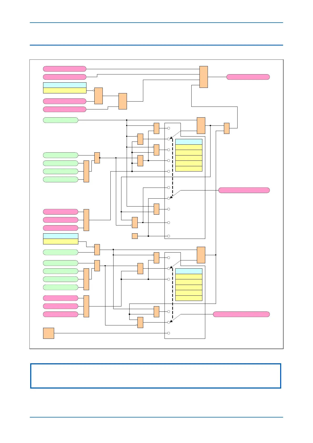
Figure 199: Circuit Breaker Fail logic - part 3
Note:
This diagram shows only first CB (CB1) of a dual-CB device. The diagrams for the second CB (CB2) follow the same principle
and are not repeated here..
P446SV Chapter 12 - CB Fail Protection
P446SV-TM-EN-1 353