V02744
Zone 8
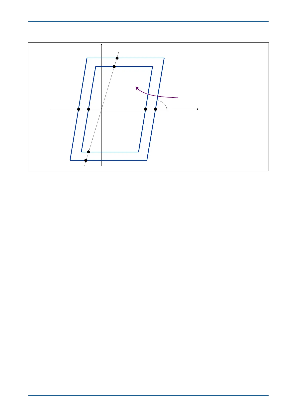
Zone 7
Resistive forward (+R)Resistive reverse (R’)
α
PSB Z7
PSB Z8
PSB Z7'
PSB Z8'
PSB R8
PSB R7PSB R7'PSB R8'
Z1 = V1/I1
Dt
+jX
ZL
Figure 121: Slow Power Swing detection characteristic
The elapsed time defines the rate of change of impedance. If the rate of change is high, the change is due to a
fault. If the rate of change is low, the protection indicates a slow power swing. So, if the time taken for the
impedance trajectory to pass through zone 8 into zone 7 is greater than the time defined by the PSB timer, a slow
power swing is deemed to be in progress. If the time taken for the impedance trajectory to pass through zone 8
into zone 7 is less than that defined by the PSB timer, it is deemed to be a fault.
In other words, a power swing is indicated if the following condition is true:
Dt > PSB Timer
Both Zone 7 and Zone 8 characteristics are based on the positive sequence impedance measurement; Z
1
= V
1
/I
1
.
The minimum current (sensitivity) needed for Zone 7 and Zone 8 measurements is 5%In.
Configuring Slow Swing Detection
Slow Swing power swing detection and blocking must first be enabled with the Slow Swing setting. After this, you
need to configure the resistive and impedance reach settings to define the concentric quadrilateral characteristics
for zones 7 and 8:
PSB R7: forward resistive reach for zone 7
PSB R7': reverse resistive reach for zone 7
PSB R8: forward resistive reach for zone 8
PSB R8': reverse resistive reach for zone 8
PSB Z7: forward impedance reach for zone 7
PSB Z7': reverse impedance reach for zone 7
PSB Z8: forward impedance reach for zone 8
PSB Z8': reverse impedance reach for zone 8
You also need to configure the impedance phase angle a. This is the same for zone 7 and zone 8. To do this you
need to set Alpha between 20° and 90°.
P446SV Chapter 10 - Power Swing Functions
P446SV-TM-EN-1 233