If I
LAG
is I2, the lines are dynamically tilted down from the fixed angle.
If I
LAG
is Iph, the fixed tilt applies.
3.2.3.4 EARTH FAULT RESISTIVE BLINDERS
The Resistive Reach settings are used to select the resistive limits of the Quadrilaterals.
The Earth Fault reach settings are set according to the positive sequence line impedance, so are generally identical
to the settings of the Phase Fault elements.
Since the Earth Fault reach settings are set according to the positive sequence line impedances, the relationship
between the positive sequence impedances and the earth-fault loop impedances needs to be understood.
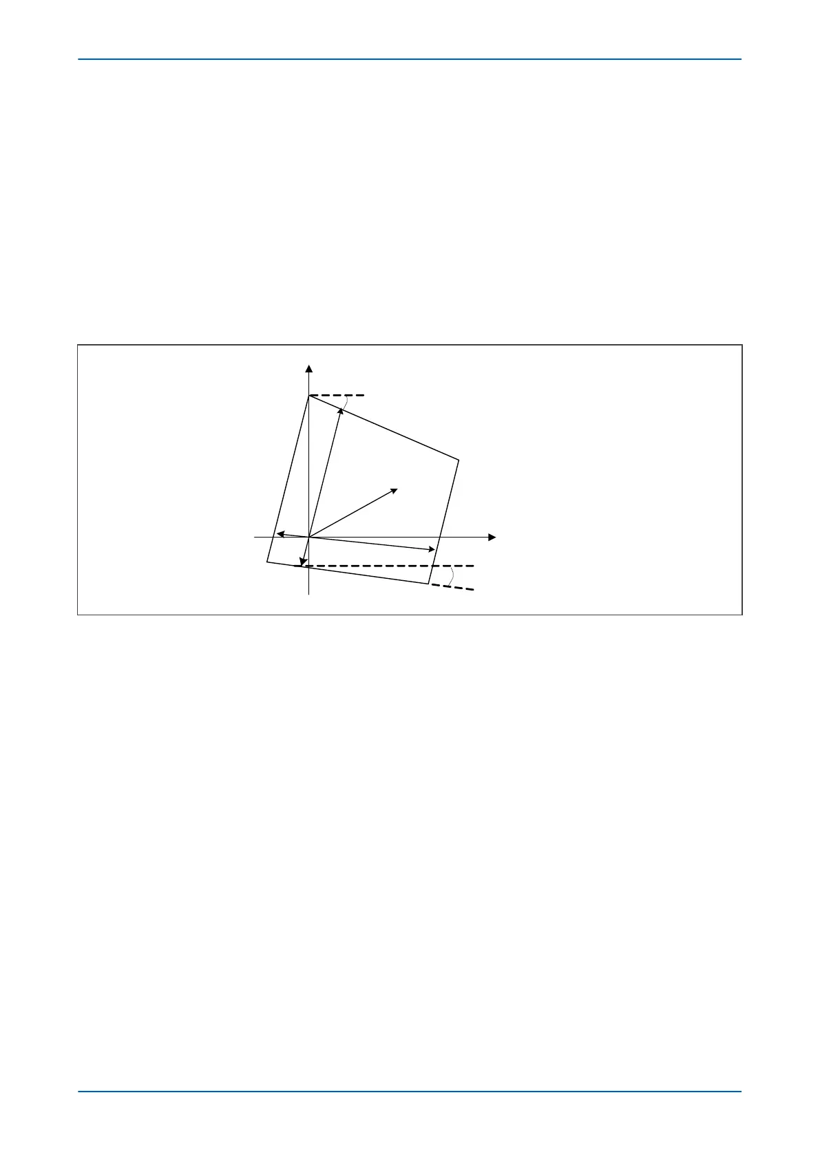
Consider the general characteristic in the Z1 plane shown in the following figure:
+R
+jX
V02734
V / I
R’
Z’
Z
1
plane
Ð
(I
ph
/ I) – 3°
Z
R
Ð
(I
ph
/ I) +
Figure 58: General characteristic in Z1 plane
R = R
LP
(Iph/I) and R’ = R’
LP
.(Iph/I)
I = Iph +k
ZN
.IN
For products that have mutual compensation, if the mutual compensation is enabled, then
I = Iph +k
ZN
.IN +k
ZM
.IM
If the healthy phase currents are much less than the current of the faulty phase and the mutual compensation is
disabled, then IN ≈ Iph (the faulty phase current) and the characteristic in the Z1 plane is simplified:
Chapter 7 - Distance Protection P446SV
136 P446SV-TM-EN-1
 Loading...


