7 INTERMICOM 64 COMMUNICATION
If the IED is used in a scheme with InterMiCOM
64
communication, you need to configure a loopback for testing
purposes.
IM64 is fibre-based. Several different fibre-optic interfaces are available. In general, 1300 nm fibres are used for
direct connection (these may be single mode or multimode). 850 nm multimode fibres are generally used with
multiplexing telecommunications equipment.
Note:
It is important that fibres used for testing are correct for the specified interface(s).
Optical fibres should be terminated with BFOC2.5 (ST2.5) connectors. For multimode applications use 50/125 µm
core fibre. Make sure fibre test leads used for measurements are long enough for mode stripping (a method of
reducing loss within the core). We recommend a minimum length of 10 m (30ft) for this.
If IEDs communicate using IEEE C37.94 compliant multiplexed electrical communication channels, a P590 is used.
This is a bidirectional optical-to-electrical signal converter. It is situated near the multiplexer, between the fibre
from the IED and the electrical interface of the multiplexer. Apply the loopback either at the P590 or the multiplexer
to ensure as much of the circuit as possible is tested. If the IED is connected to a multiplexer, the loopback testing
is exactly the same whether connected directly or via a multiplexer. The P590 interface units require additional
tests (see P590 documentation).
To enable IM64, set the InterMiCOM64 cell in the CONFIGURATION column to Enable.
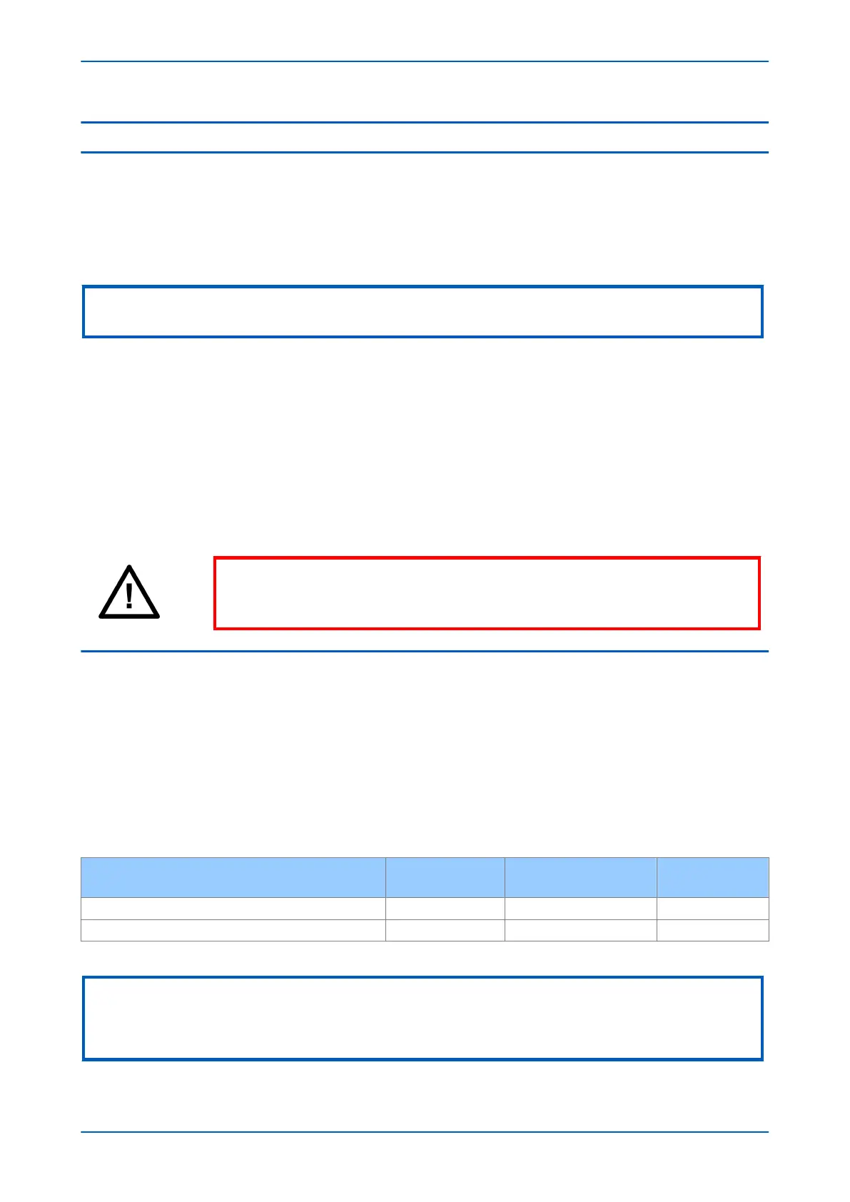
Warning:
NEVER look directly into the transmit port or the end of an optical fibre, as this could
severely damage your eyes.
7.1 CHECKING THE INTERFACE
Before carrying out the loopback test, you need to check that the interface is transmitting a suitable signal. To
check this ...
1. Set COMMISSIONING TEST > Loopback Mode to External.
2. Using an appropriate fibre-optic cable, connect the Channel 1 transmitter (TX1) to an optical power meter.
Check that the average power transmitted is within the range given in the following table.
3. Record the transmit power level.
4. Repeat for Channel 2 if applicable.
Power
850 nm
multi-mode
1300 nm
multi-mode
1300/1550 nm
single-mode
Maximum transmitter power (average value) -19.8 dBm -3 dBm -3 dBm
Minimum transmitter power (average value) -22.8 dBm -9 dBm -9 dBm
Note:
If CONFIGURATION > InterMiCOM64 is set to Enable, the signals normally sent and received by and from the
communications interface are routed to and from the signals defined in the Programmable Scheme Logic. If, however,
COMMISSION TESTS > IM64 Test Mode is set to Enabled, an IM64 test pattern is transmitted instead.
Chapter 24 - Commissioning Instructions P446SV
626 P446SV-TM-EN-1