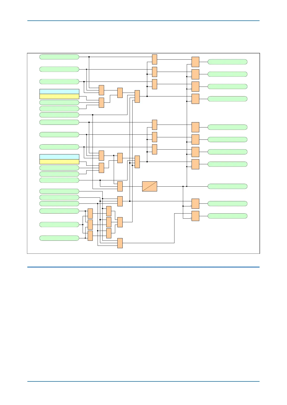
5.22.1 CB TRIP CONVERSION LOGIC DIAGRAM
V03387
Trip Inputs A
1
R
Q
S
CB1 Trip OutputA
Trip Inputs B
1
R
Q
S
CB1 Trip OutputB
Trip Inputs C
1
R
Q
S
CB1 Trip OutputC
CB1Tripping Mode
3 Pole
1
1
AR Force CB1 3P
Force 3PTrip CB1
CB1 Trip I/P 3Ph
&
1
R
Q
S
CB1 Trip 3ph
Trip Inputs A
1
R
Q
S
CB2 Trip OutputA
Trip Inputs B
1
R
Q
S
CB2 Trip OutputB
Trip Inputs C
1
R
Q
S
CB2 Trip OutputC
CB2Tripping Mode
3 Pole
1
1AR Force CB2 3P
Force 3PTrip CB2
CB2 Trip I/P 3Ph
&
1
R
Q
S
CB2 Trip 3ph
1
Any Trip
Dwell
100 ms
1
1
1
Pole Dead A
Pole Dead B
Pole Dead C
Trip Inputs A
Trip Inputs B
Trip Inputs C
&
&
&
1
&
R
Q
S
R
Q
S
2/3 Ph Fault
3 Ph Fault
≥
2
530
531
532
530
531
532
858
533
529
1485
1604
1608
530
531
532
892
893
894
523
524
525
526
1601
1602
1603
1600
522
527
528
Figure 188: Circuit Breaker Trip Conversion Logic Diagram (Module 63)
5.23
MONITOR CHECKS FOR CB CLOSURE
For single-phase Autoreclose neither voltage nor synchronisation checks are needed as synchronising power
should be flowing in the two healthy phases. For three-phase Autorelcose, for the first shot (and only the first shot),
you can choose to attempt reclosure without performing a synchronisation check. The setting to permit
Autoreclose without checking synchronising conditions is CB SC Shot 1.
Otherwise, synchronising checks on voltages, relative frequencies, and relative phase angles are needed to ensure
that sympathetic conditions exist before CB closure is attempted.
The following diagrams detail the Monitor Checks for CB closure.
P446SV Chapter 11 - Autoreclose
P446SV-TM-EN-1 331

 Loading...


