V02738-2
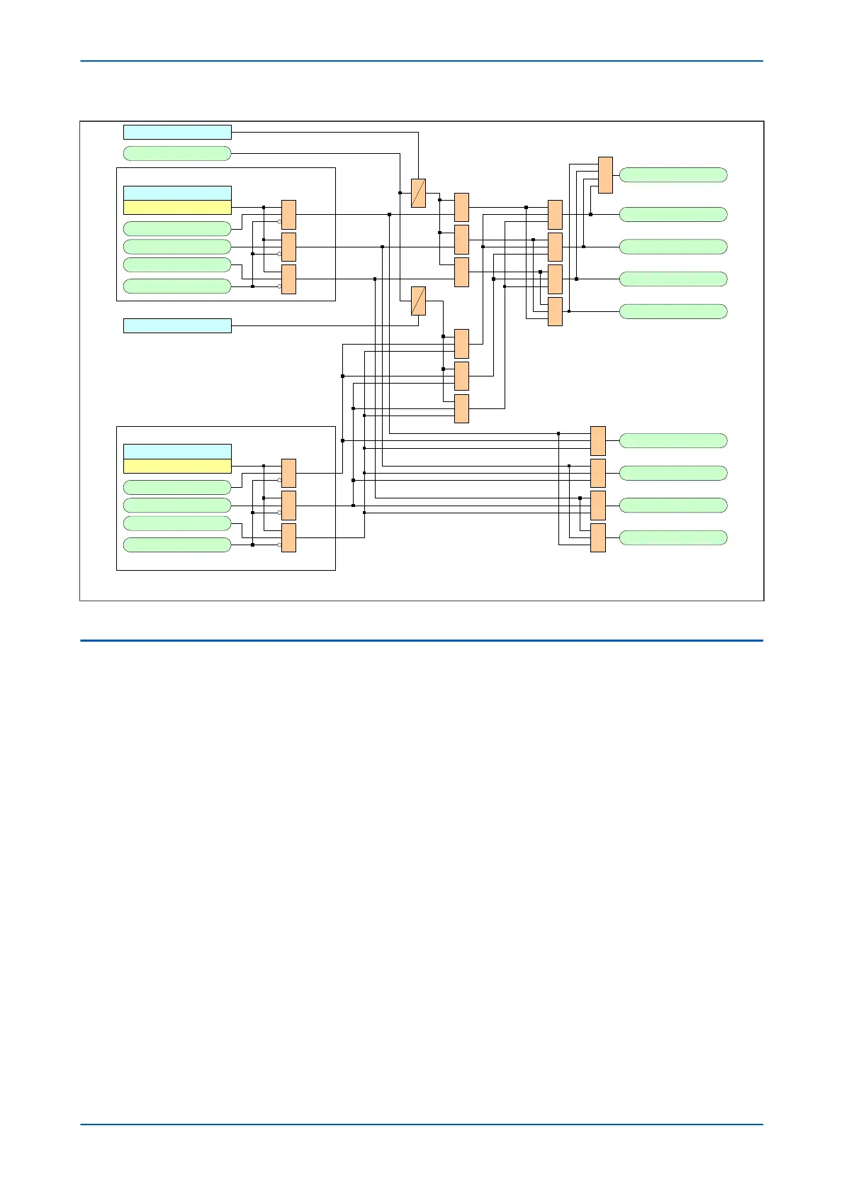
tZ1 Gnd. Delay
Zone 1 A Start
Zone 1 Trip
1 Zone 1 A Trip
1 Zone 1 B Trip
1 Zone 1 C Trip
1 Zone 1 N Trip
Zone 1 B Start
Zone 1 C Start
Zone 1 N Start
Note: This diagram shows Zone 1 only. The other zones follow the same principles .
tZ1 Ph. Delay
&
&
&
1
1
1
1
1
&
&
&
Any Dist Start
Zone1 AN Element
Block Zone 1 Gnd
Zone 1 Gnd Stat.
Enabled
Zone1 BN Element
Zone1 CN Element
&
&
&
Zone 1 Ground Elements
Zone1 AB Element
Block Zone 1 Phs
Zone 1 Ph Status
Enabled
Zone1 BC Element
Zone1 CA Element
&
&
&
Zone 1 Phase Elements
1691
960
961
962
384
963
964
965
385
608
609
610
611
612
741
742
743
744
Figure 105: Alternative basic timer start scheme mode logic
3.2
BASIC SCHEME SETTING
The Zone 1 time delay (tZ1) is generally set to zero, giving instantaneous operation.
The Zone 2 time delay (tZ2) is set to co-ordinate with Zone 1 fault clearance time for adjacent lines. The total fault
clearance time consists of the downstream Zone 1 operating time plus the associated breaker operating time.
Allowance must also be made for the Zone 2 elements to reset following clearance of an adjacent line fault and
also for a safety margin. A typical minimum Zone 2 time delay is of the order of 200 ms.
The Zone 3 time delay (tZ3) is typically set with the same considerations made for the Zone 2 time delay, except
that the delay needs to co-ordinate with the downstream Zone 2 fault clearance. A typical minimum Zone 3
operating time would be in the region of 400 ms.
The Zone 4 time delay (tZ4) needs to coordinate with any protection for adjacent lines in the protection’s reverse
direction.
Separate time delays can be applied to both phase and ground fault zones, for example where ground fault delays
are set longer to time grade with external ground/earth overcurrent protection.
Any zone (#) which may reach through a power transformer reactance, and measure secondary side faults within
that impedance zone should have a small time delay applied. This is to avoid tripping on the inrush current when
energizing the transformer.
As a general rule, if the Zone Reach setting is greater than 50% of the transformer reactance, set the Zone delay to
be 100 ms or greater. Alternatively, the 2nd harmonic detector output (which is available in the Programmable
Scheme Logic) may be used to block zones that may be at risk of tripping on inrush current. Settings for the inrush
detector are found in the SUPERVISION column.
The figure below shows the typical application of the Basic scheme.
P446SV Chapter 9 - Non-Aided Schemes
P446SV-TM-EN-1 215