When the breaker is closed, supervision current passes through opto input 1 and the trip coil. When the breaker is
open current flows through opto input 2 and the trip coil. No supervision of the trip path is provided whilst the
breaker is open. Any fault in the trip path will only be detected on CB closing, after a 400 ms delay.
4.2.1 RESISTOR VALUES
Optional resistors R1 and R2 can be added to prevent tripping of the CB if either opto-input is shorted. The table
below shows the appropriate resistor value and voltage setting for this scheme.
Trip Circuit Voltage Opto Voltage Setting with R1 Fitted Resistor R1 and R2 (ohms)
48/54 24/27 1.2k
110/125 48/54 2.7k
220/250 110/125 5.2k
Warning:
This Scheme is not compatible with Trip Circuit voltages of less than 48 V.
4.2.2 PSL FOR TCS SCHEME 2
Opto Input 1
V01218
&
*Output Relay
LED
User Alarm
0
400
dropoff
straight
0
0
Latching
Opto Input 2
1
pickup
0
50
CB Aux 3ph(52-A)
CB Aux 3ph(52-B)
*NC stands for Normally Closed.
Figure 251: PSL for TCS Scheme 2
In TCS scheme 2, both opto-inputs must be low before a trip circuit fail alarm is given.
4.3
TRIP CIRCUIT SUPERVISION SCHEME 3
TCS Scheme 3 is designed to provide supervision of the trip coil with the breaker open or closed. It provides pre-
closing supervision of the trip path. Since only one opto-input is used, this scheme is not compatible with latched
trip contacts. If you require CB status monitoring, further opto-inputs must be used.
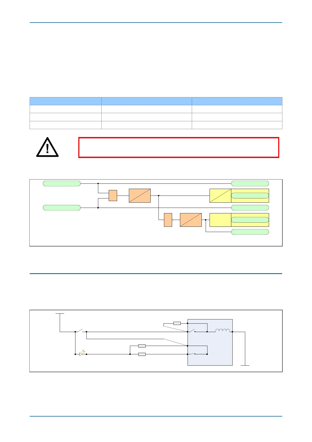
V01216
52A
52B
Output Relay
+ve
-ve
Opto-input
Circuit Breaker
R3
R2
R1
Trip path
Trip coil
Figure 252: TCS Scheme 3
When the CB is closed, supervision current passes through the opto-input, resistor R2 and the trip coil. When the
CB is open, current flows through the opto-input, resistors R1 and R2 (in parallel), resistor R3 and the trip coil. The
Chapter 17 - Supervision P446SV
456 P446SV-TM-EN-1