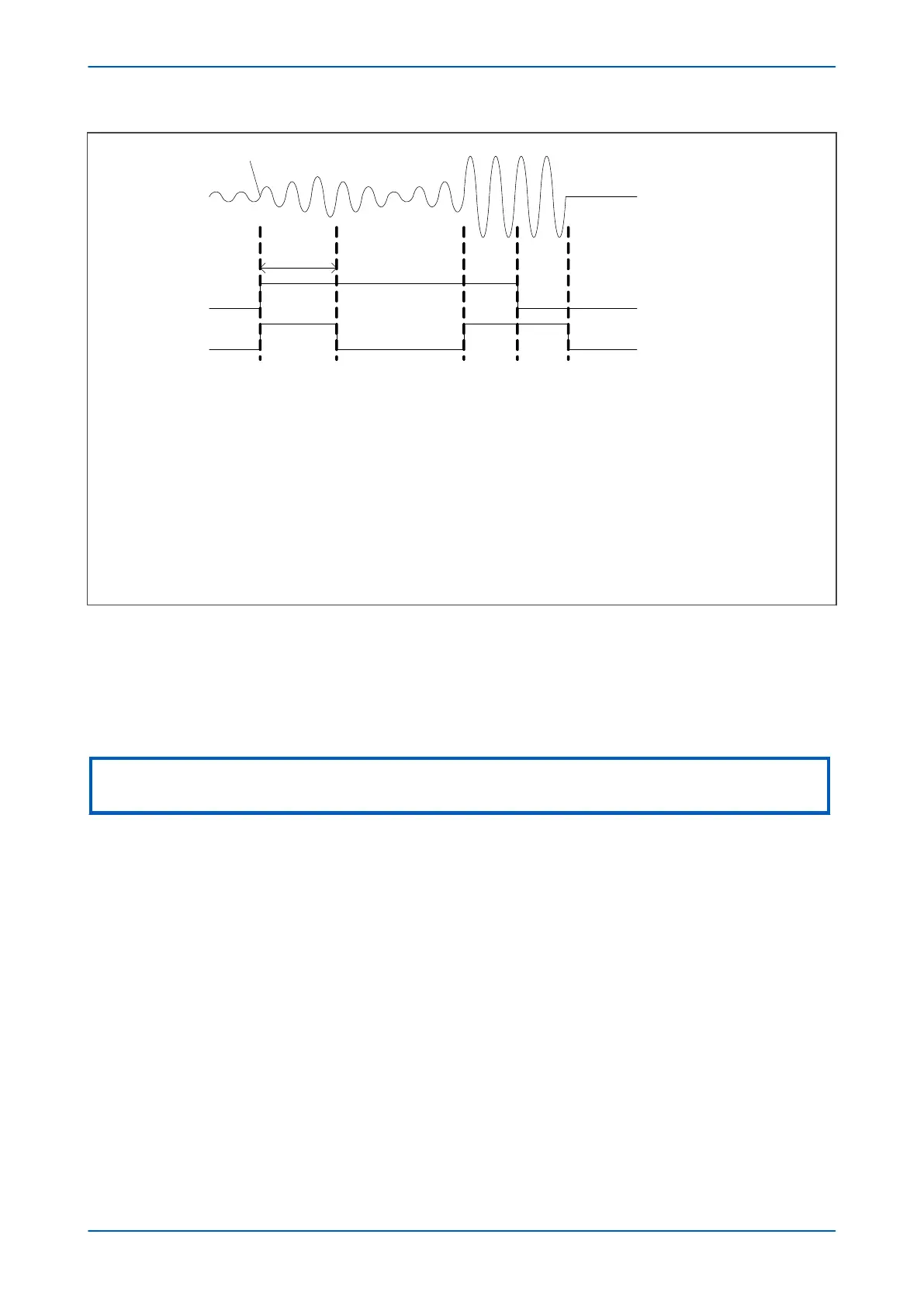
Start of
power swing
i (t)
3 cycles
PH1
PH2
t
1
t
2
t
3
t
4
t
5
t1: D i exceeds threshold 1 (5%In), so PH1 and PH2 go high
t
2
: Threshold 2 invoked (10%In). PH2 goes low on account of threshold being increased (from 5%IN to 10%In).
PH1 remains high, because there continues to be a D i
t
3
: Fault inception. D i exceeds threshold 2 (10%In), so PH2 goes high
t4: 2 cycles after fault inception , PH1 goes low
t
5
: Fault cleared, so PH2 goes low
V02771
Figure 120: Phase selector timing for fault during a power swing
3.1.2
SLOW POWER SWING DETECTION
For slow power swings (0.5Hz and below) where the superimposed current may remain below the minimum 5%In
threshold needed for the superimposed current (DI) detector, a different detection method is used. This method is
called Slow Swing detection. This method requires the Slow Swing setting to be enabled.
Note:
If the Slow Swing feature is not Enabled, very slow power swings (< 0.5 Hz) may not be detected.
The Slow Swing method is based on changing impedance measurements and uses a pair of configurable
concentric quadrilateral zones on the impedance plane (Zone 7 and Zone 8). Since power swings don’t involve
earth, the impedance measurements are based on positive sequence quantities and only phase-phase
measurements are necessary. The characteristic is shown in the following figure:
Chapter 10 - Power Swing Functions P446SV
232 P446SV-TM-EN-1