EasyManua.ls Logo

GE MiCOM P40

GE MiCOM P40
962 pages
To Next Page IconTo Next Page
To Previous Page IconTo Previous Page
Loading...
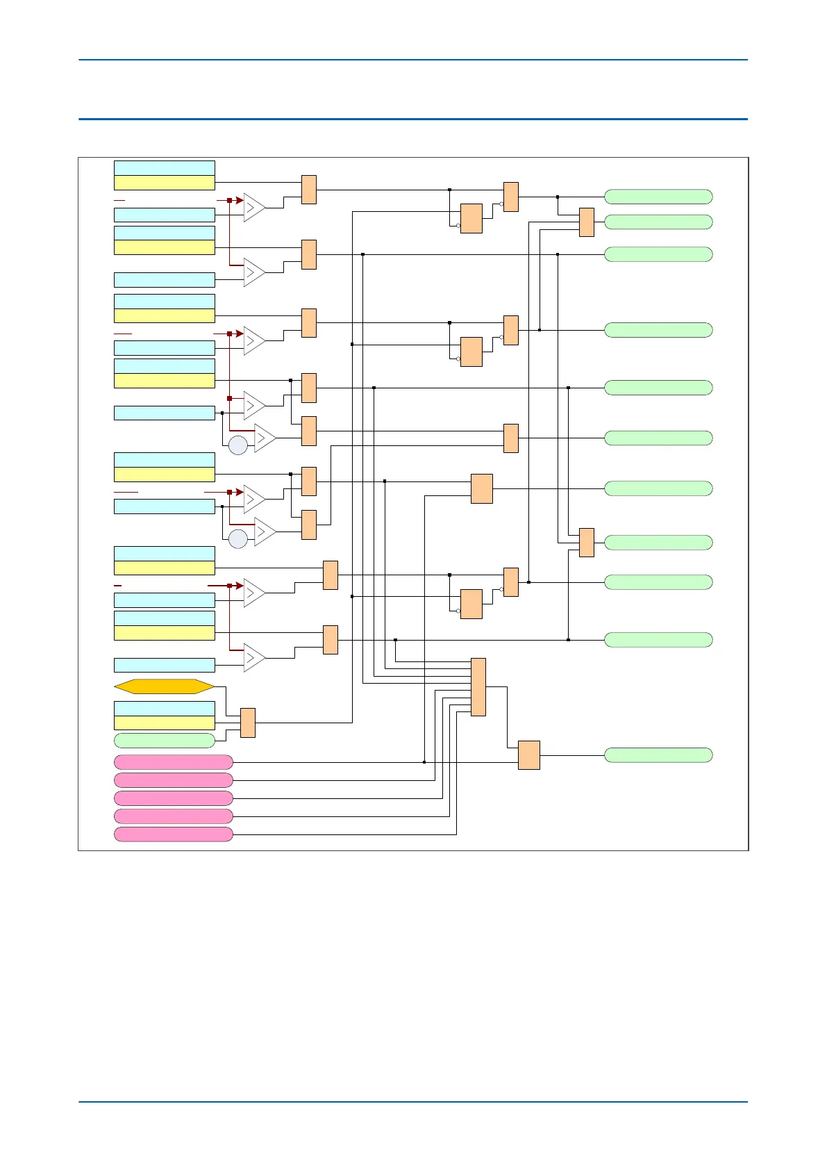
5.6 CB CONDITION MONITORING LOGIC
V01283
CB1 I^ Maint
CB1 I^ Maint
Alarm Enabled
&
CB1 I^ Maint
&
1 CB1 Monitor Alm
R
Q
S
CB1 I^ Lockout
&
CB1 I^ Lockout
Alarm Enabled
CB1 I^ Lockout
No.CB1 Ops Maint
Alarm Enabled
&
No.CB1 Ops Maint
&
R
Q
S
No.CB1 Ops Maint
No.CB1 Ops Lock
&
No.CB1 Ops Lock
Alarm Enabled
No.CB1 Ops Lock
-1
&
CB1FltFreqLock
Alarm Enabled
&
CB1FltFreqCount
R
Q
S
CB1FaultFreqLock
-1
&
1 CB1 Pre-Lockout
CB1 Time Maint
CB1 Time Maint
Alarm Enabled
&
CB1 Time Maint
&
R
Q
S
CB1 Time Lockout
&
CB1 Time Lockout
Alarm Enabled
CB1 Time Lockout
1 CB1 Mon LO Alarm
Reset CB1 Data
Yes 1
Rst CB1 Data
1
Control CB1 Unhealthy
CB1 Control no Check Synch
CB1 failed to trip
CB1 failed to close
Reset CB1 Lockout Alarm
R
Q
S
CB1 LO Alarm
Clear Alarms
Greatest broken current total
Max no. of CB operations
Fault frequency count
Greatest CB operate time
Figure 231: CB1 Condition Monitoring logic diagram
Chapter 16 - Monitoring and Control P446SV
422 P446SV-TM-EN-1

Table of Contents

Related product manuals